What Is A Purely Resistive Circuit Circuit Diagram Phasor Diagram

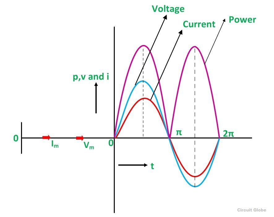
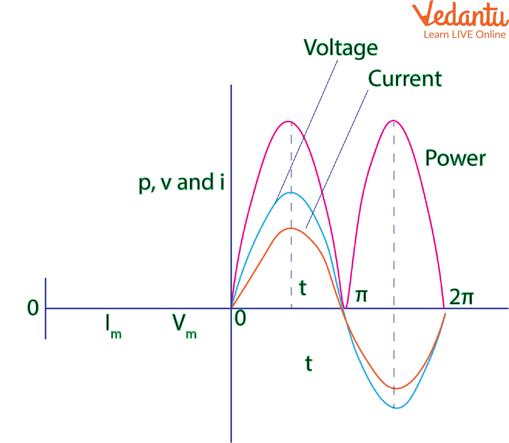
What Is A Pure Resistive Circuit Phasor Diagram And Waveform Phasor diagram of purely resistive circuit. from the phasor diagram shown in figure (2), it is clear that the a.c voltage and current are in phase i.e., there is no phase difference between them. impedance of purely resistive circuit. In the purely resistive circuit, the power is dissipated by the resistors and the phase of the voltage and current remains same i.e., both the voltage and current reach their maximum value at the same time. the resistor is the passive device which neither produce nor consume electric power. it converts the electrical energy into heat.

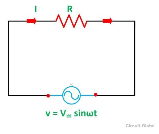
Purely Resistive Purely Inductive And Purely Capacitive Circuits For J In this section, let’s look at the characteristics and phasor diagrams of pure resistive, pure inductive, and pure capacitive circuits. purely resistive circuit. definition: a purely resistive circuit has a very negligible amount of inductance such that the reactance offered by such circuits is very small when compared to the resistance even. Phasor diagrams and phasor algebra. phasor diagrams are a graphical way of representing the magnitude and directional relationship between two or more alternating quantities. phasor diagrams present a graphical representation, plotted on a coordinate system, of the phase relationship between the voltages and currents within passive components. A purely resistive circuit is a circuit that has inductance so small that at its typical frequency, its reactance is insignificant as compared to its resistance. furthermore, in a purely resistive circuit, the whole of the utilized voltage is consumed in overcoming the ohmic resistance of the circuit itself. Phasor diagram for a resistor. resistor: a resistor is a passive two terminal electrical component that implements electrical resistance as a circuit element. in an ac circuit, a resistor will resist the flow of electrons, turning electrical energy into heat. in a purely resistive ac circuit, the current and voltage are in phase with each other.

Phasor Diagram For Purely Resistive Circuit A purely resistive circuit is a circuit that has inductance so small that at its typical frequency, its reactance is insignificant as compared to its resistance. furthermore, in a purely resistive circuit, the whole of the utilized voltage is consumed in overcoming the ohmic resistance of the circuit itself. Phasor diagram for a resistor. resistor: a resistor is a passive two terminal electrical component that implements electrical resistance as a circuit element. in an ac circuit, a resistor will resist the flow of electrons, turning electrical energy into heat. in a purely resistive ac circuit, the current and voltage are in phase with each other. Unity power factor (pf) – purely resistive (r) circuit phasor diagram when a circuit is completely resistive (r), the complex impedance has a zero reactance (x = 0) value: using ohm’s law again to calculate the complex current (i) drawn by the circuit, we find that when the complex impedance has a zero reactance (x = 0) value, the current. The vertical axis on a phasor diagram could be either the voltage or the current, depending on the phasor that is being examined. in addition, several quantities can be depicted on the same phasor diagram. for example, both the current \(i r(t)\) and the voltage \(v r(t)\) are shown in the diagram of figure \(\pageindex{3b}\).

Comments are closed.