What Is A Pure Inductive Circuit Phasor Diagram Waveform Circuit

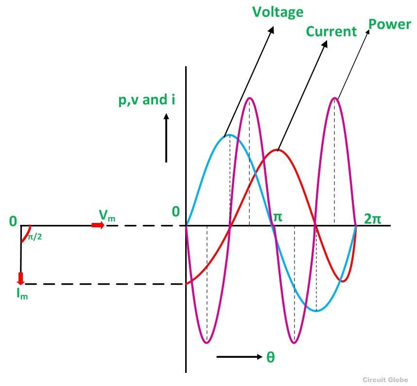
What Is A Pure Inductive Circuit Phasor Diagram Waveform Circuit Phasor diagram and waveform of pure inductive circuit the voltage, current and power waveform are shown in blue, red and pink colours respectively. when the values of voltage and current are at its peak as a positive value, the power is also positive and similarly, when the voltage and current give negative waveform the power will also become. Phasor diagram of purely inductive circuit. the phasor diagram of a purely inductive circuit is shown in figure (2). from figure (2) it is clear that the current in the circuit lag behind the voltage by 90º. impedance of purely inductive circuit. impedance ‘z’ of any circuit is given by, \[z=\sqrt{{{r}^{2}} {{x}^{2}}}\] where,.

What Is A Pure Inductive Circuit Phasor Diagram Waveform Circuit The phase of an alternating quantity at any instant in time can be represented by phasor diagrams. thus phasor diagrams can be thought of as representing “functions of time”. a complete sine wave can be constructed by a single vector rotating anti clockwise at an angular velocity of ω = 2πƒ, where ƒ denotes the frequency of the waveform. Or p = 0 i.e., average power consumption in a purely inductive circuit is zero. purely capacitive circuit definition, phasor diagram, and derivation of formula. definition: in this type of circuit, upon supply of alternative voltage, the capacitor gets charged first in one direction and next in another direction. hence, it charges itself when. The opposition to current flow through an ac inductor is called inductive reactance and which depends lineally on the supply frequency. when connected to an ac supply, the current flowing through an inductive coil produces a self induced emf opposing the emf that initially set up the current. for a time varying circuit which contains ac. Cosϕ = r z, as diagramed in. phasor diagram for an rlc series circuit: phasor diagram for an rlc series circuit. \phi is the phase angle, equal to the phase difference between the voltage and current. for example, at the resonant frequency (ν0 = 1 2π√lc) or in a purely resistive circuit, z=r, so that cosϕ=1.

What Is A Pure Inductive Circuit Phasor Diagram Waveform Circuit The opposition to current flow through an ac inductor is called inductive reactance and which depends lineally on the supply frequency. when connected to an ac supply, the current flowing through an inductive coil produces a self induced emf opposing the emf that initially set up the current. for a time varying circuit which contains ac. Cosϕ = r z, as diagramed in. phasor diagram for an rlc series circuit: phasor diagram for an rlc series circuit. \phi is the phase angle, equal to the phase difference between the voltage and current. for example, at the resonant frequency (ν0 = 1 2π√lc) or in a purely resistive circuit, z=r, so that cosϕ=1. This results in a voltage wave that is 90° out of phase with the current wave. looking at the graph, the voltage wave seems to have a “head start” on the current wave; the voltage “leads” the current and the current “lags” behind the voltage. current lags voltage by 90° in a pure inductive circuit. A pure inductive circuit is one in which the only quantity in the circuit is inductance (l), with no other components such as resistance or capacitance. the current in this type of circuit lags behind the voltage by 90 degrees. inductive reactance is the resistance to current flow via an ac inductor, and it is proportional to the supply frequency.

Comments are closed.