Vdo Tachometer Wiring Diagram

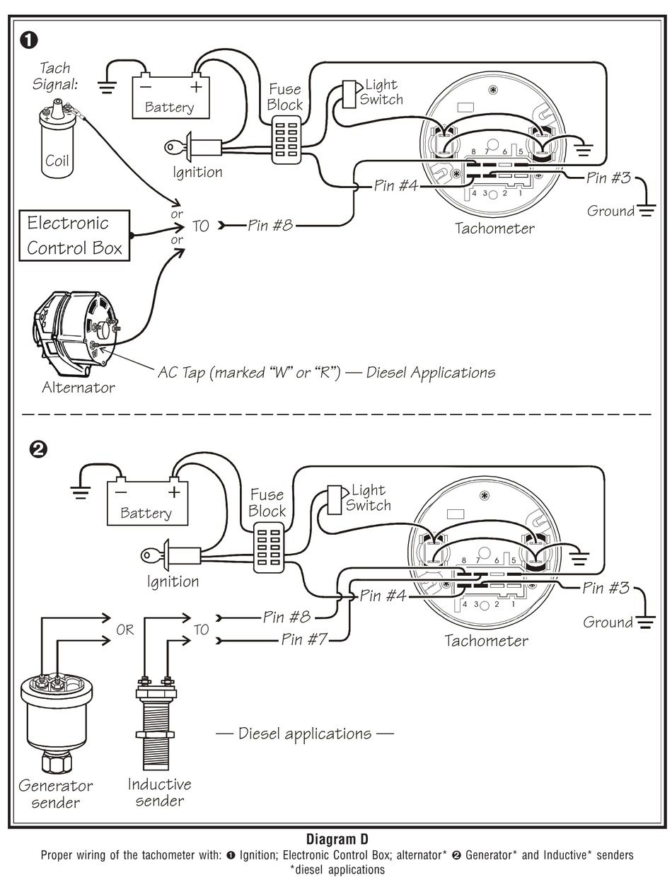
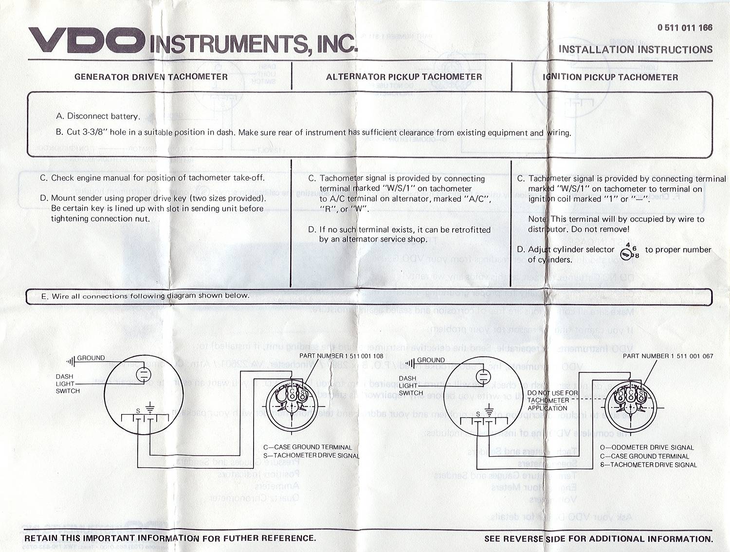
Proper Wiring Of The Tachometer Siemens Vdo Installation And Learn how to wire a vdo tachometer to measure the engine's rpm accurately. follow the wiring diagram and connect the power, ground, ignition, and signal wires correctly. This web page provides safety information and installation instructions for vdo viewline tachometer without display. it does not contain the wiring diagram for the tachometer, but advises to follow the electrical wiring diagram and use appropriate tools and cables.

Vdo Tachometer Wiring Diagram S tachometer signal input ( ) ground ( 12v) and signal ( ) parts list item description qty 1 gauge 1 2 clamp & nuts 1 3 instruction sheet 1 read these instructions thoroughly before installation. do not deviate from assembly or wiring diagram. always disconnect battery ground before making any electrical connections. View and download vdo tachometer installation instructions manual online. tachometer measuring instruments pdf manual download. 5000041 01 vdo instructions pg 1 rev b.ai. 07 15 08. 1.0 general information. the vdo programmable tachometers featured in this installation manual are programmed with an inductive sender. these instructions describe the installation, wiring, calibration and operation of all such tachometers. each tachometer's analog display clearly shows the. 12k rpm xtreme tachometer. ttp: usa.vdo instruction sheet #revision xxxpea. rpm recall:press “up” arrow to display current peak rpm. lue. the value will display for 5 seconds before returning to 0 rpmto clear peak r. call value press and hold “up”. l pointer returns to 0. the led will flash and then go.

Comments are closed.