Vdo Tach Wiring Plan

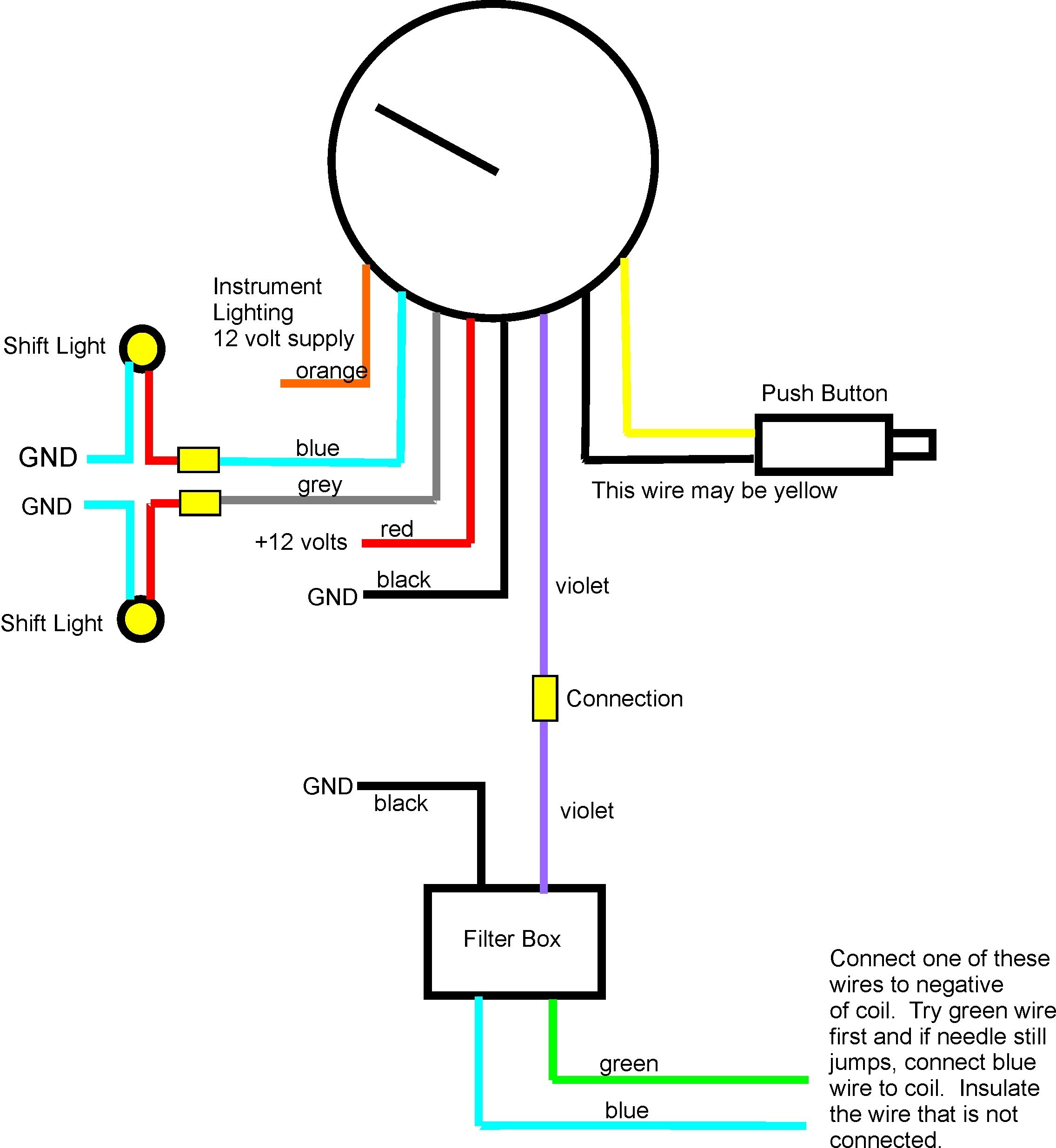
Vdo Tach Wiring Plan 5000041 01 vdo instructions pg 1 rev b.ai. 07 15 08. 1.0 general information. the vdo programmable tachometers featured in this installation manual are programmed with an inductive sender. these instructions describe the installation, wiring, calibration and operation of all such tachometers. each tachometer's analog display clearly shows the. Tachometer receives its signal from. (note: when using a magnetic flywheel sender, the sender is non polarized so it does not matter which wire is connected to the tachometer s terminal and which is connected to ground) expressed or implied warranties, including any implied terminal description switched power (12v).

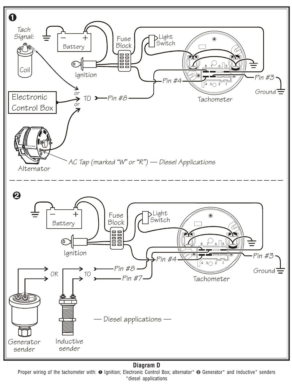
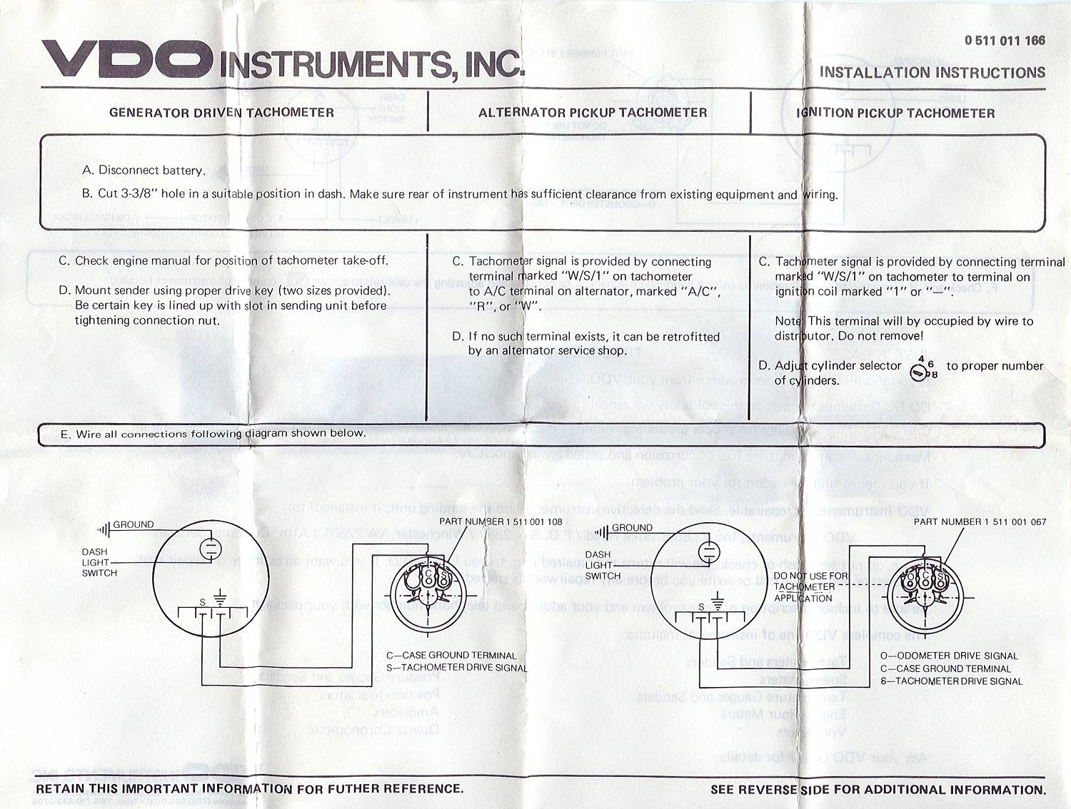
Proper Wiring Of The Tachometer Siemens Vdo Installation And After you have completed the wiring, test the vdo tachometer to ensure it is functioning properly. start the engine and observe the tachometer reading. it should accurately display the engine speed. if not, double check your wiring connections and consult the tachometer’s user manual for troubleshooting tips. The panel width may be within a range of 2 to 20 mm. the drill hole must have a diameter of 86 mm. do not. drill holes or ports in load bearing or stabilizing stays or tie bars! note the. necessary clearance behind the drill hole or port at the installation location. required mounting depth: 65 mm. drill. View and download vdo tachometer installation instructions manual online. tachometer measuring instruments pdf manual download. Instruction sheet #0 515 012 037 rev. instructions for the installation and operation of the programmable tachometer are contained herein. use is restricted to 12 volt or 24 volt negative ground electrical systems.c. caution; read these instructions thoroughly before installing the tachometer. do not deviate from assembly or wiring instructions.

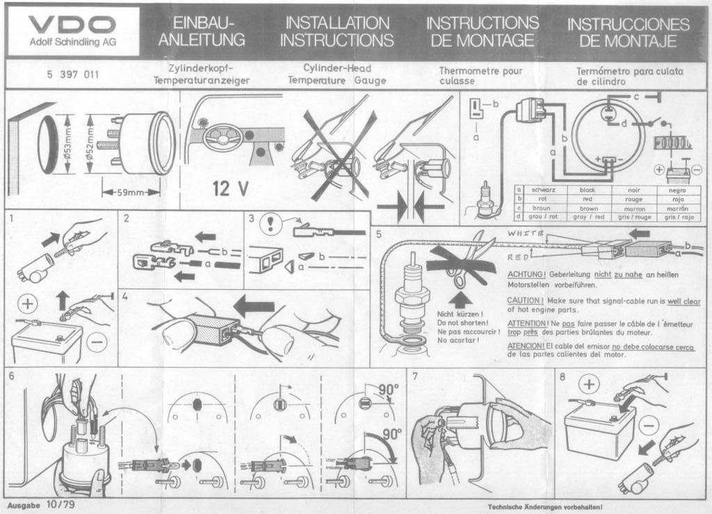
Vdo Tach Wiring Plan View and download vdo tachometer installation instructions manual online. tachometer measuring instruments pdf manual download. Instruction sheet #0 515 012 037 rev. instructions for the installation and operation of the programmable tachometer are contained herein. use is restricted to 12 volt or 24 volt negative ground electrical systems.c. caution; read these instructions thoroughly before installing the tachometer. do not deviate from assembly or wiring instructions. Page 2 installation instructions: viewline 85 mm 01 14 tachometer tu00 0752 5807102 1 10 procedures for installing vdo viewline instruments before beginning, turn off the ignition and remove the ignition key. if necessary, remove the main circuit switch. disconnect the negative terminal on the battery. page 3 installation instructions: viewline. Tach with display 85mm. 1. select the desired mounting location of the instrument. 2. depending on your mounting situations it might be. necessary to configure the gauge before installation. see page 2 setting up the tachometer. 3. mount the gauge and secure with the vdo spin lok™.

Vdo Tachometer Wiring Schematic Page 2 installation instructions: viewline 85 mm 01 14 tachometer tu00 0752 5807102 1 10 procedures for installing vdo viewline instruments before beginning, turn off the ignition and remove the ignition key. if necessary, remove the main circuit switch. disconnect the negative terminal on the battery. page 3 installation instructions: viewline. Tach with display 85mm. 1. select the desired mounting location of the instrument. 2. depending on your mounting situations it might be. necessary to configure the gauge before installation. see page 2 setting up the tachometer. 3. mount the gauge and secure with the vdo spin lok™.

Vdo Tach Wiring Instructions Diagram

Comments are closed.