Transmission Cooler Flow Direction Types Diagram Brake Experts

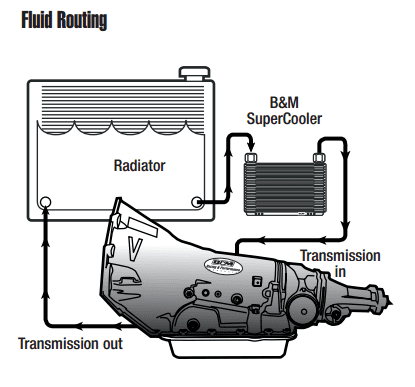
Transmission Cooler Flow Direction Types Diagram Brake Experts As already mentioned, the flow direction of the transmission cooler is such that the top hose attachment is the hotline, and the bottom one is the cold line. the hotline is the fluid returning from the transmission, and the cold line is the fluid returning into the transmission. however, that’s just a rule of thumb, so it could be the other. 6l80 transmission cooler flow direction. the transmission fluid low of the 6l80 goes as follows: if you do not have an external transmission cooler, the cooler line flow goes as follows: lower cooler line > lower radiator port > upper radiator port > back to upper transmission line. powered by wordpress and hitmag .

Transmission Cooler Flow Direction Types Diagram 4r100. hope this helps. the return line to the 4r70w is the top line on the transmission. so the top line on the transmission is the cool line in from the rad. bottom line of transmission is hot line out to the rad. 4r100 front (forward) line on the transmission is the out line (hot) to the rad. the rear line on the transmission is the in line. When you are finished with the installation, mounting, and plumbing, your transmission cooling diagram will look like this: transmission >feed line >radiator(stock cooler) >aftermarket tranny cooler >return line >transmission it is ideal to splice the transmission cooler into the return line, so that way the coolant flows through the stock in. Start engine while engine is cold. depress brake pedal, place transmission in drive for no more than 10 seconds. stop engine. identify oil return line by feeling both oil lines (3&4). coolest line is oil return line. method 2 (requires an observer) – check oil flow direction (fig c) fig. place container under oil line (3) and disconnect oil. The optimal direction of transmission cooler flow is from the transmission to the cooler and then back to the transmission. this allows the transmission fluid to: absorb heat from the transmission. get cooled in the cooler. return to the transmission to repeat the process. this guide will discuss the intricacies of transmission cooler flow.

Transmission Cooler Flow Direction Types Diagram Start engine while engine is cold. depress brake pedal, place transmission in drive for no more than 10 seconds. stop engine. identify oil return line by feeling both oil lines (3&4). coolest line is oil return line. method 2 (requires an observer) – check oil flow direction (fig c) fig. place container under oil line (3) and disconnect oil. The optimal direction of transmission cooler flow is from the transmission to the cooler and then back to the transmission. this allows the transmission fluid to: absorb heat from the transmission. get cooled in the cooler. return to the transmission to repeat the process. this guide will discuss the intricacies of transmission cooler flow. The cooler core will flow in either direction, there is no specified inlet or outlet port. note: diagram #2 cooler installation (see diagram #3) 1. identify the 4 mounting rods, 4 mounting clips and 4 1x1 foam pads. 2. one by one, install the 4 mounting rods thru the transmission cooler. 3. take the 1x1 foam pads supplied, peel off the paper. You see how the spools can stage mid circuit, which further restricts converter and cooler flow. this effect varies with 46 or 47 rh re cooler lines and may become a problem as head pressure nears 80 psi or more (see figure 2 ). the most effective verification technique is to temporarily bypass the cooler circuit and re test.

Transmission Cooler Flow Direction Types Diagram The cooler core will flow in either direction, there is no specified inlet or outlet port. note: diagram #2 cooler installation (see diagram #3) 1. identify the 4 mounting rods, 4 mounting clips and 4 1x1 foam pads. 2. one by one, install the 4 mounting rods thru the transmission cooler. 3. take the 1x1 foam pads supplied, peel off the paper. You see how the spools can stage mid circuit, which further restricts converter and cooler flow. this effect varies with 46 or 47 rh re cooler lines and may become a problem as head pressure nears 80 psi or more (see figure 2 ). the most effective verification technique is to temporarily bypass the cooler circuit and re test.

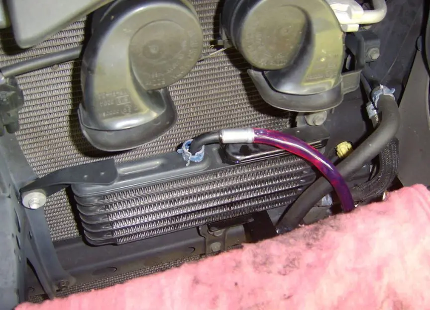
Transmission Cooler Installation How To Install A Transmission Cooler

Comments are closed.