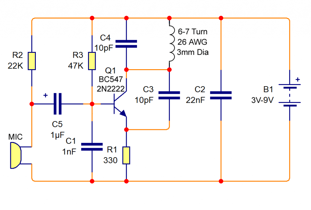
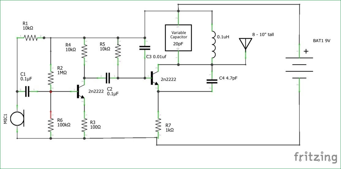
Top 4 Fm Transmitter Circuit Diagram

Best Fm Transmitter Circuit Diagram Using Bc547 The circuit can also be used as a remote control transmitter. fm demodulator using pll – this is a good circuit of an fm demodulator with a schematic diagram, a design of fm demodulator, and working of pll with block diagram. this will definitely be useful for your educational purposes. fm stereo demodulator using an7415 – stereo. Top 4 fm transmitter circuit diagram👉get a free trial of altium designer with 365 and 25% off your purchase :👉 altium yt zaferyildiz 👈👉lea.

Fm Transmitter Circuit Diagram And Working в Electronics Project Design of oscillator circuit: a) selection of tank circuit components – l1 and c6: we know the frequency of oscillations is given by. f = 1 (2∏√lc) here we require a frequency between 88 mhz to 100 mhz. let us select a 0.2uh inductor. this gives value of c6 to be around 12pf. Fm transmitter circuits are popular in educational projects, providing hands on experience in electronics and wireless communication. these projects focus on simplicity and ease of construction. Make sure to use the correct voltage and polarity to avoid damaging the circuit. step 5: connect the antenna. the antenna is crucial for broadcasting the fm signal. connect the antenna to the output of the oscillator circuit, ensuring proper connections for optimal signal transmission. step 6: fine tune the circuit. Fm transmitter circuit diagram and explanation. connect the components as shown in the simple fm transmitter circuit below. this is how this simple fm transmitter circuit looks on breadboard. the audio output signal from the microphone is usually small, the first transistor thus performs the job of amplifying that signal to a level good enough.

4 Stage Fm Transmitter Scheme Electronic Schematic Diagram Make sure to use the correct voltage and polarity to avoid damaging the circuit. step 5: connect the antenna. the antenna is crucial for broadcasting the fm signal. connect the antenna to the output of the oscillator circuit, ensuring proper connections for optimal signal transmission. step 6: fine tune the circuit. Fm transmitter circuit diagram and explanation. connect the components as shown in the simple fm transmitter circuit below. this is how this simple fm transmitter circuit looks on breadboard. the audio output signal from the microphone is usually small, the first transistor thus performs the job of amplifying that signal to a level good enough. An fm transmitter circuit is an electronic circuit used to modulate and broadcast radio waves that carry audio signals. the most common type of fm transmitter used in consumer electronics is the frequency modulation (fm) transmitter, which operates on a frequency range between 88 and 108 mhz. this range is referred to as the “fm band.”. Step 13: tune the transmitter. turn on your radio then tune it to your desired channel frequency. you'll get more range from the vacant channels. don't touch the coil, just turn the trimmer capacitor until you hear a feedback from the radio.

Simple Fm Transmitter Circuit Diagram And Making It On Breadboard An fm transmitter circuit is an electronic circuit used to modulate and broadcast radio waves that carry audio signals. the most common type of fm transmitter used in consumer electronics is the frequency modulation (fm) transmitter, which operates on a frequency range between 88 and 108 mhz. this range is referred to as the “fm band.”. Step 13: tune the transmitter. turn on your radio then tune it to your desired channel frequency. you'll get more range from the vacant channels. don't touch the coil, just turn the trimmer capacitor until you hear a feedback from the radio.

Comments are closed.