Temperature Controlled Fan Electronics Lab

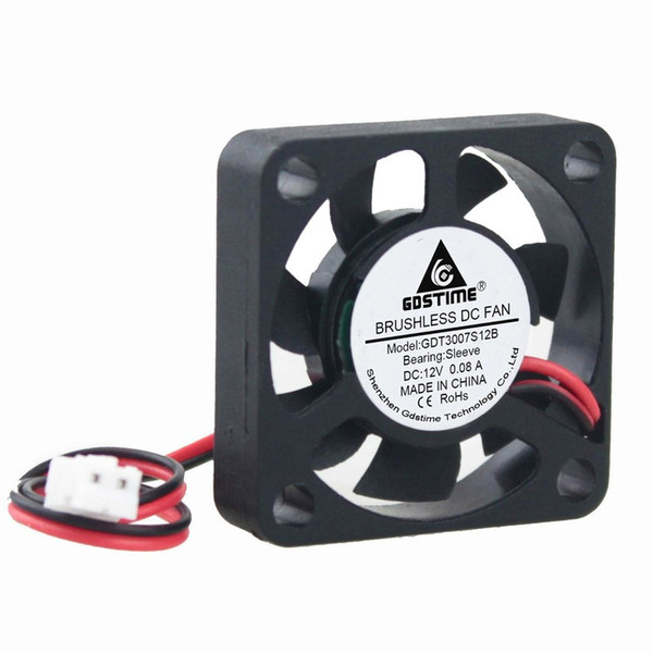
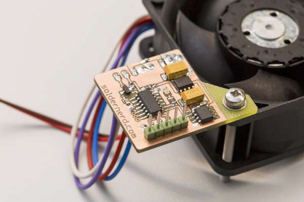
Temperature Controlled Fan Using Attiny10 Electronics Lab Ahmad al shalabi and bassma karbouj show us how to control a dc fan using easy to find components. the fan works when temperature reach into pre specified threshold. the purpose of this project is creating a cooling system by controlling in a dc fan in a simple way without using microcontrollers or arduino but by using electronic components that it’s very simple and available. Temperature controlled fan using attiny10. the electrons movement in electronic components lead to the generation of heat which when beyond certain thresholds, prevents some components from functioning properly and in others could lead to a catastrophic breakdown. for this reason, the topics of ventilation, overheating, and cooling are.

Temperature Controlled Fan Electronics Lab A temperature controlled dc fan is a system which automatically turns on a dc fan when the ambient temperature increases above a certain limit. generally, electronic devices produce more heat. so this heat should be reduced in order to protect the device. there are many ways to reduce this heat. one way is to switch on the fan spontaneously. How to make temperature controlled fan using arduino and dht11: temperature controlled fans have become a popular diy project for keeping your surroundings cool automatically. in this blog, we will guide you through creating a temperature controlled fan using an arduino board. with just a few electronic componen…. Working of automatic temperature controlled fan using thermistor. it works on the principle of thermistor. in this circuit, pin 3 (non inverting terminal of op amp 741) is connected with the potentiometer and pin 2 (inverting terminal) is connected in between of r2 and rt1 (thermistor) which is making a voltage divider circuit. Here the temperature controlled fan will act to the temperature changes. we have also written a blog on what temperature sensors are, if you are interested feel free to read that as well to understand more about these types of sensors. we are going to do this with a dht11 temperature and humidity sensor. it can be done in various other ways as.

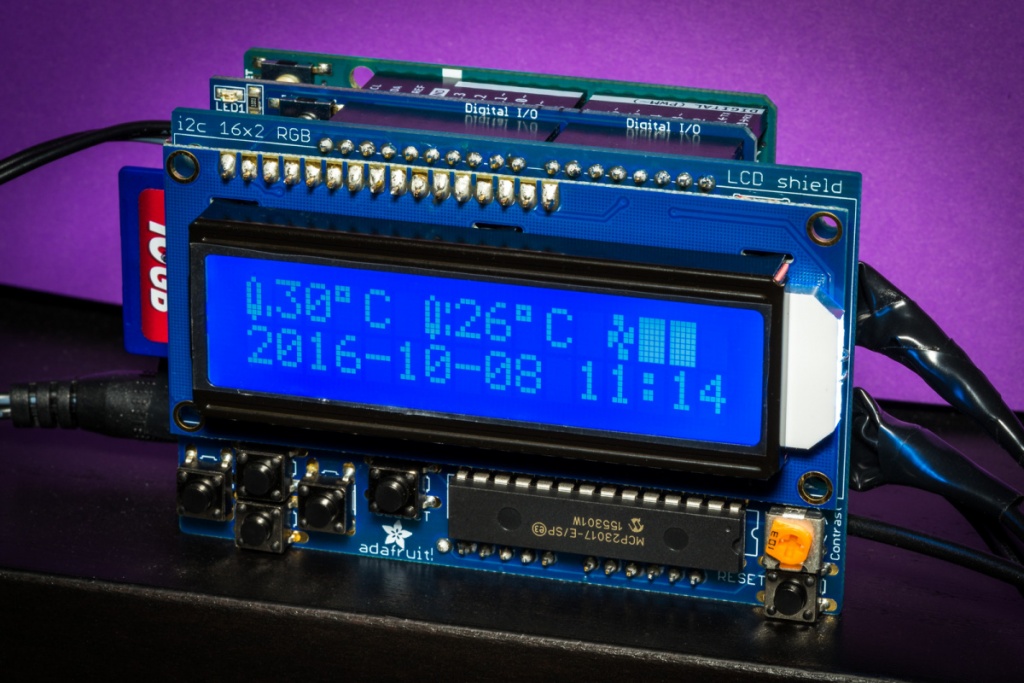
Temperature Controlled Fan Electronics Lab Working of automatic temperature controlled fan using thermistor. it works on the principle of thermistor. in this circuit, pin 3 (non inverting terminal of op amp 741) is connected with the potentiometer and pin 2 (inverting terminal) is connected in between of r2 and rt1 (thermistor) which is making a voltage divider circuit. Here the temperature controlled fan will act to the temperature changes. we have also written a blog on what temperature sensors are, if you are interested feel free to read that as well to understand more about these types of sensors. we are going to do this with a dht11 temperature and humidity sensor. it can be done in various other ways as. The fan and the plug were later added using photoshop. the diagram consists of an arduino,a relay, an lm35 sensor, an ac fan, and a plug. the temperature controlled fan circuit is very simple. the lm35 sensor has 3 pins vcc, gnd and analog output pin. the vcc pin will be connected to the 5v pin of arduino. Arduino code for temperature controlled fan. first, we include the library for lcd and dht sensor and then define pin for lcd, dht sensor and for fan. then initialize all the things in setup loop. and in loop by using dht function reads dht sensor and then using some dht functions we extract temperature and display these on lcd.

Comments are closed.