Subwoofer Low Pass Filter Circuit Diagram 4558 How To Make Subwoofe

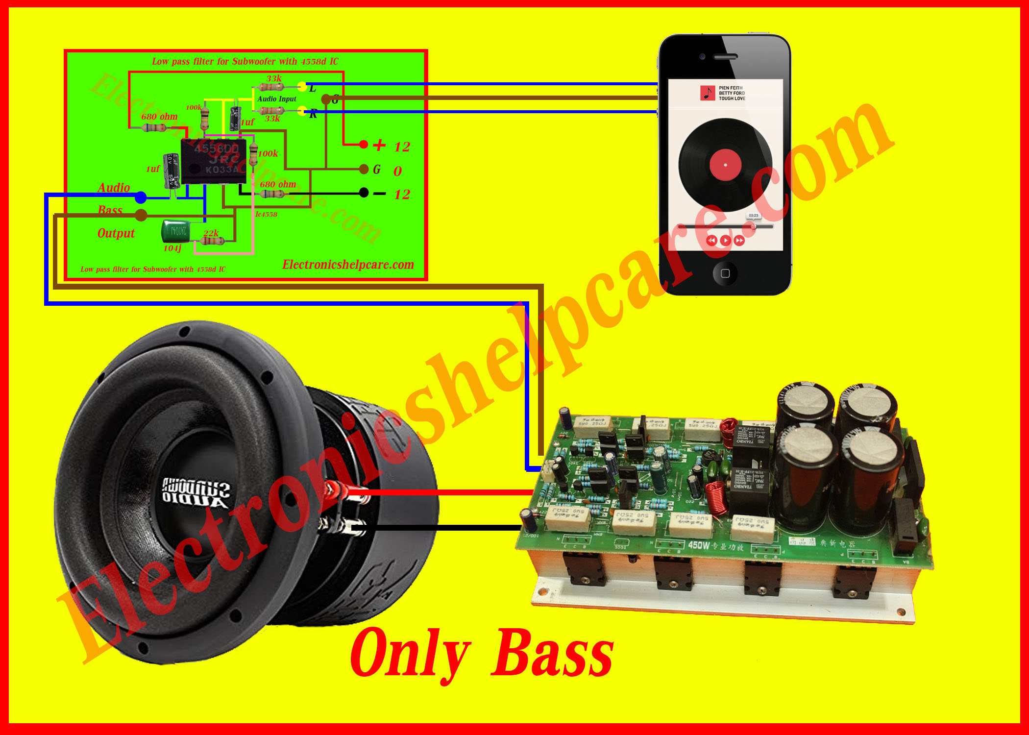
Subwoofer Bass Booster 4558 Ic Low Pass Filter Tronicspro Step 6: success. we did it! we just built our own low pass filter for subwoofer. low pass filter for subwoofer with 4558d ic: in this project i will show you how you can make a low pass filter with 4558d ic for subwoofer. let's get started!. This video is part of the knowledge to share with everyone who wants to know about the benefits. i hope video can help everyone, thank you very much.download.

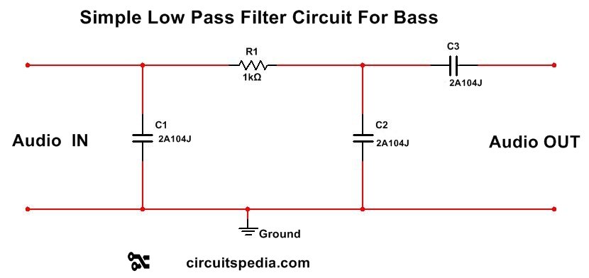
Subwoofer Low Pass Filter Circuit Diagram 4558 How To M $4 off on the first component order lcsc my tools list which i usually use in the video bit.ly tools listpcb layout goo.gl wq. Subwoofer low pass filter using transistors. the circuit diagram exhibits an active low pass filter layout that can be assigned any preferred cut off point, across a large range easily by computing a couple of magnitudes for four capacitors. the filter includes an rc network and a pair of npn pnp bjts. the transistor specifications shown could. A subwoofer low pass filter is a crucial component in any sound system that requires high quality bass. the low pass filter helps to remove unwanted frequency signals that may cause distortion and noise in the system. this low pass filter can help to eliminate high frequency signals that cannot be heard or identified by the human ear. Low pass filter circuit wiring .4558 ic board subwoofer low pass filter . amzn.to 3hdcm92bass treble amzn.to 3e58gy62.1 board .ht.

Subwoofer Low Pass Filter Circuit A subwoofer low pass filter is a crucial component in any sound system that requires high quality bass. the low pass filter helps to remove unwanted frequency signals that may cause distortion and noise in the system. this low pass filter can help to eliminate high frequency signals that cannot be heard or identified by the human ear. Low pass filter circuit wiring .4558 ic board subwoofer low pass filter . amzn.to 3hdcm92bass treble amzn.to 3e58gy62.1 board .ht. The circuit that i publish, is a circuit of modules that use the subwoofer amplifier ic op amp 4558 which acts as a reinforcement of bass tones (subwoofer) assisted of it's by the workings of some supporting components such as resistors, capacitors. the workings of this circuit adds to the gain on the frequency of low tone (lpf), so that the. The lm4558 ic is designed for low distortion, low noise, and high gain applications. the 4558 ic subwoofer bass booster low pass filter circuit uses a combination of resistor capacitor networks, op amps, and inductors to filter and enhance low frequency sounds. the low pass filter network filters out the high frequency signals, leaving only the.

Subwoofer 4558 Ic Bass Treble Circuit Diagram How To Make Bass The circuit that i publish, is a circuit of modules that use the subwoofer amplifier ic op amp 4558 which acts as a reinforcement of bass tones (subwoofer) assisted of it's by the workings of some supporting components such as resistors, capacitors. the workings of this circuit adds to the gain on the frequency of low tone (lpf), so that the. The lm4558 ic is designed for low distortion, low noise, and high gain applications. the 4558 ic subwoofer bass booster low pass filter circuit uses a combination of resistor capacitor networks, op amps, and inductors to filter and enhance low frequency sounds. the low pass filter network filters out the high frequency signals, leaving only the.

Subwoofer Circuit Diagram Using Ic 4558

Comments are closed.