Solar Power Inverter Circuit Diagram Guide

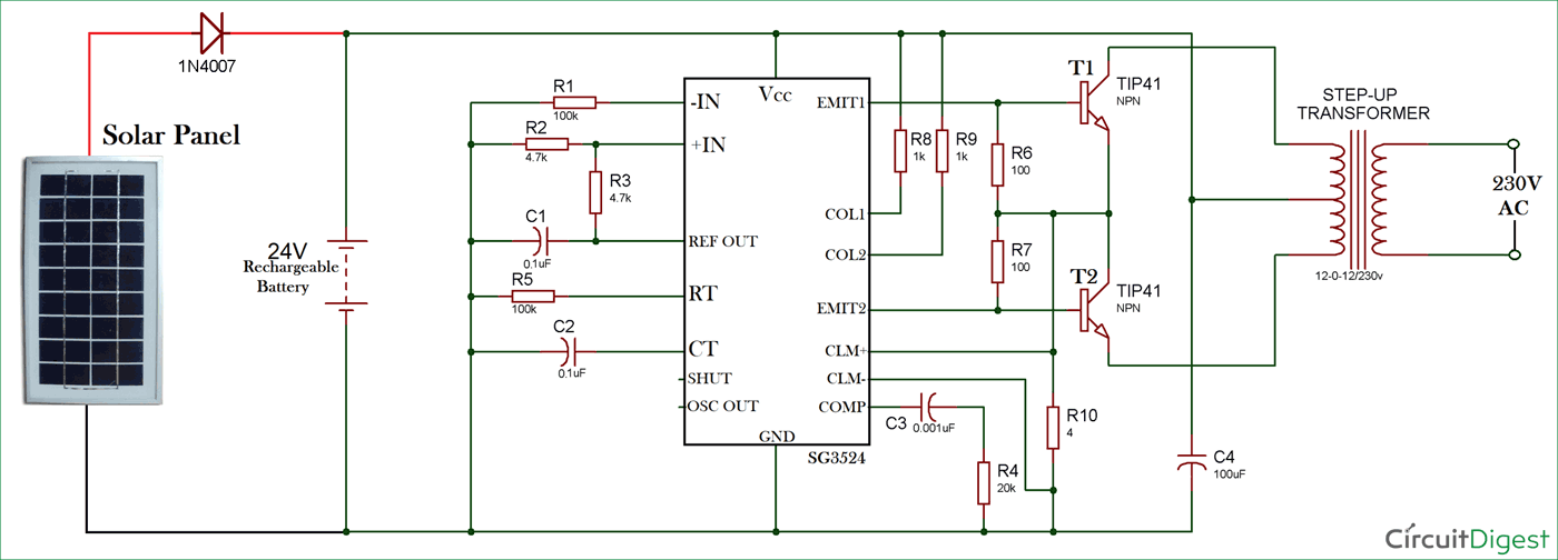
Schematic Circuit Diagram Of Solar Inverter In conclusion, the solar panel and inverter connection diagram demonstrates the flow of power from the solar panel to the inverter and further distribution to the electrical panel of a building. this connection allows for the utilization of solar energy as a renewable and sustainable source of power. understanding the basics of solar panel systems. With the current drive towards sustainable energy, free solar inverter circuit diagrams are a crucial resource for anyone looking to build a solar energy system. such diagrams provide an invaluable step by step guide on how to build a solar inverter, connecting batteries, solar panels and other components to create a reliable energy source.

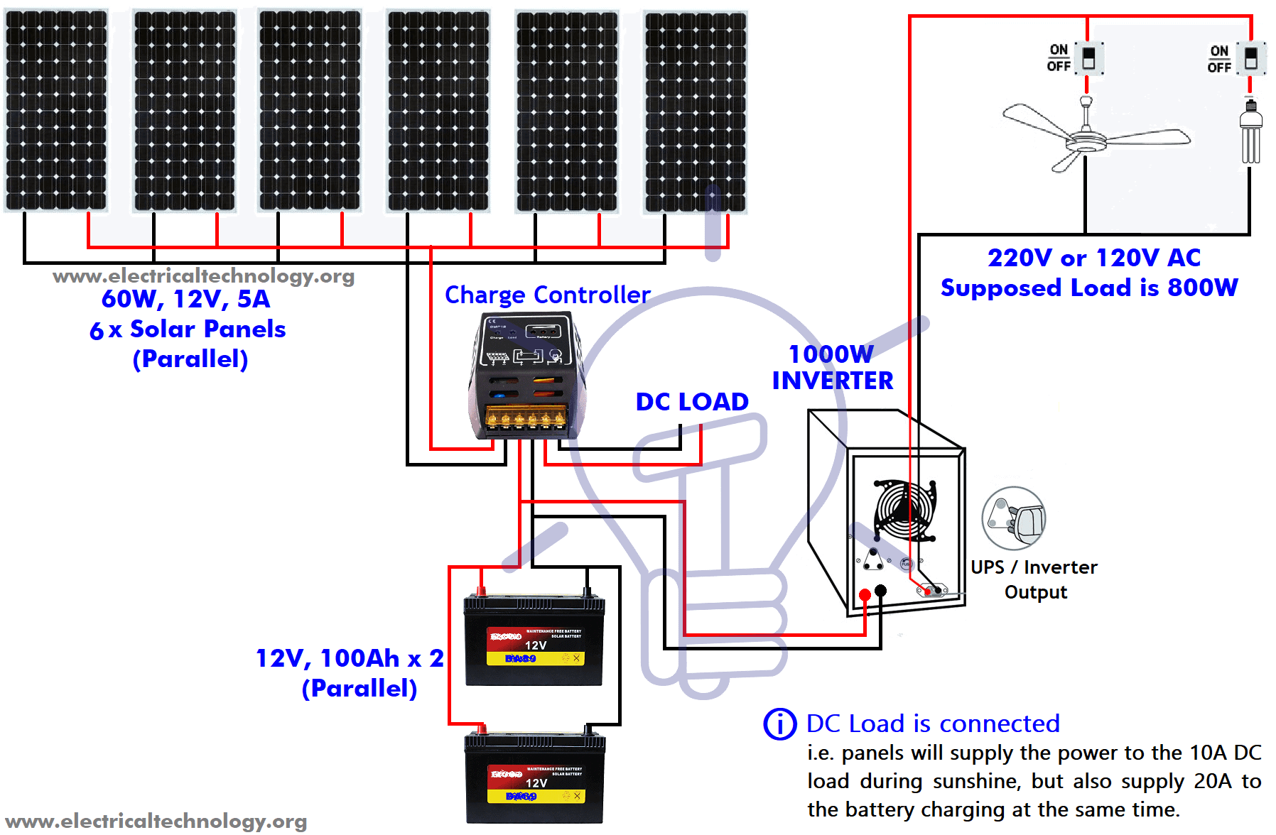
Solar Power Inverter Circuit Diagram Guide If you’re using an ecoflow delta pro with 3 x 400w portable solar panels, the diagram is simple. you simply connect each panel together in series and then plug them into the solar charge input. on the other hand, if you’re connecting 42 x ecoflow 400w rigid solar panels to 3 x delta pro ultra inverters home backup batteries, the diagram. The connection diagram for a solar inverter typically includes the dc input terminals for connecting the solar panels, the ac output terminals for connecting to the electrical grid, and various other connections for monitoring, communication, and grounding purposes. in conclusion, solar inverters are an essential component of a solar power. Here are the connection steps to follow: step 1: locate the positive and negative terminals of your panel connection and the corresponding dc input terminals of your inverter. step 2: connect the positive terminal of your panel connection to the positive terminal of your inverter, using a red cable and a connector. Table of contents. how to connect solar panels to an inverter. step 1: determine your power needs. step 2: choose the right inverter. step 3: wiring your solar panels in series or parallel. step 4: connect your solar panels to the inverter. step 5: connect the inverter to the battery or grid.

Solar Panel Wiring Guide Here are the connection steps to follow: step 1: locate the positive and negative terminals of your panel connection and the corresponding dc input terminals of your inverter. step 2: connect the positive terminal of your panel connection to the positive terminal of your inverter, using a red cable and a connector. Table of contents. how to connect solar panels to an inverter. step 1: determine your power needs. step 2: choose the right inverter. step 3: wiring your solar panels in series or parallel. step 4: connect your solar panels to the inverter. step 5: connect the inverter to the battery or grid. The diagram shows the connection between the inverter and the grid, enabling a seamless transfer of power between the solar system and the utility grid. understanding the wiring diagram of a hybrid solar inverter is crucial for installers and homeowners alike. it ensures a proper installation and efficient operation of the solar power system. Wiring in series refers to connecting the plus of one panel or battery to the minus of another ( ). this adds the voltages of all panels together but leaves the current (amps) the same. for example, if you have four panels wired in series, each with 20 volts and five amps, the output would be 80 volts and five amps. advantage.

Circuit Diagram Of Solar Power Inverter The diagram shows the connection between the inverter and the grid, enabling a seamless transfer of power between the solar system and the utility grid. understanding the wiring diagram of a hybrid solar inverter is crucial for installers and homeowners alike. it ensures a proper installation and efficient operation of the solar power system. Wiring in series refers to connecting the plus of one panel or battery to the minus of another ( ). this adds the voltages of all panels together but leaves the current (amps) the same. for example, if you have four panels wired in series, each with 20 volts and five amps, the output would be 80 volts and five amps. advantage.

Comments are closed.