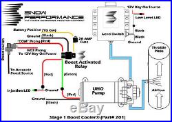
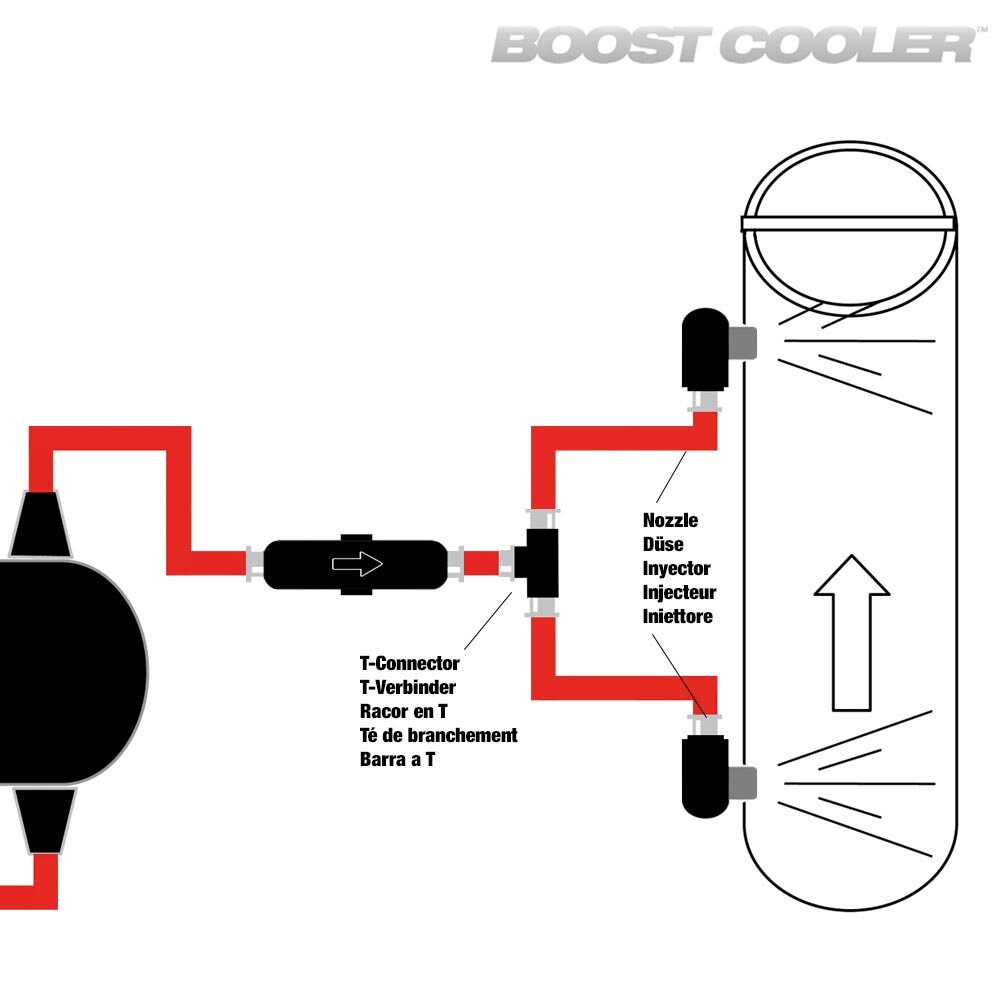
Snow Performance Boost Cooler Wiring Diagram

Snow Perfromance Stage 2 Boost Cooler Progressive Water Methanol K you want to be alerted. typical placement is 1 3rd of the tank height. step 3: remove the cap from the tank and feed p. ll wires through hole until level sensor is seated against plastic stopper.step 4: reinstall t. e clear rubber gasket, plastic ring, and plastic nut onto the level. nsor.step 5: push clear rubber in until flush with o. Page 8: wiring diagram. part# 210 210 brd wiring diagram step 1 vc 50 wiring boost source step 1: mount controller in desired location using a 52 mm gauge pod. step 2: slide boost hose (black silicon hose supplied in kit) over the black boost line coming from the controller and sure with a wire tie.

Snow Performance Gas Stage 1 Boost Cooler Water Methanol Injection Kit E with your stage 2 boost cooler install. e system follow the below steps. step 1: arm the system by putting the key in the ignition step 2: make sure fluid is in the water meth tank step 3: remove nozzle from intake l. cation and place in highly visible area step 4: hit the prime button on. Download this manual. congratulations on your purchase of a snow performance boost cooler® gas water methanol. injection kit! keep these instructions for reference. first locate the part# of your injection system. which can be found on the front of the boost cooler® box. use this number to identify which set of. caution. View and download snow performance 20130 installation instructions manual online. mustang stage 3 boost cooler water methanol injection system. 20130 pdf manual download. Part# 310 310 brd wiring diagram step 1 stage 3 controller wiring boost source step 1: mount controller in desired location using double sided tape. ensure mounting surface is clean before applying tape. step 2: connect boost hose (black silicon hose supplied in kit) to the clear blue boost line coming from the controller.

Water Injection Boost Cooler Dual Nozzle Upgrade Proline Water View and download snow performance 20130 installation instructions manual online. mustang stage 3 boost cooler water methanol injection system. 20130 pdf manual download. Part# 310 310 brd wiring diagram step 1 stage 3 controller wiring boost source step 1: mount controller in desired location using double sided tape. ensure mounting surface is clean before applying tape. step 2: connect boost hose (black silicon hose supplied in kit) to the clear blue boost line coming from the controller. Tank you want to be alerted. typical placement is 1 3rd of the tank height.step 3: remove the cap from the tank and feed p. ll wires through hole until level sensor is seated against plastic stopper.step 4: reinstall t. e clear rubber gasket, plastic ring, and plastic nut onto the level. sensor.step 5: push clear rubber in until flush with. Best performance. because the stage 3™ system injects more frequently, the fluid consumption rate will be higher than other boost cooler systems. the stage 3™ system has been coupled with the snow performance 7 gallon reservoir to provide a large fluid tank that fits well into the bed of a truck. this will provide the longest range.

Comments are closed.