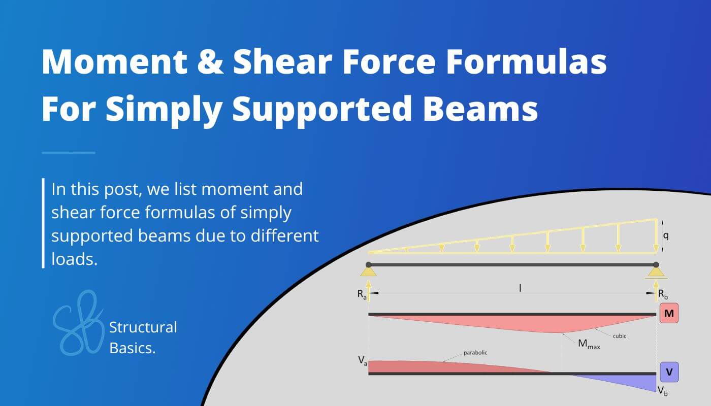
Simply Supported Beam вђ Moment Shear Force Formulas Due To Different

Simply Supported Beam вђ Moment Shear Force Formulas Du R a = r b = 1 2 ⋅ q ⋅ l. those formulas can also be calculated by hand. check out this article if you want to learn in depth how to calculate the bending moments, shear and reaction forces by hand. 2. simply supported beam – uniformly distributed load (udl) at midspan (formulas) bending moment and shear force diagram | simply supported. 6. cantilever beam – 3 point loads (formulas) 7. cantilever beam – triangular load (formulas) 8. cantilever beam – external moment (formulas) now, before we get started, always remember that the unit of the bending moment is kilonewton meter [k n m] and kilonewton [k n] for the shear forces when in europe. but now, let’s get started.

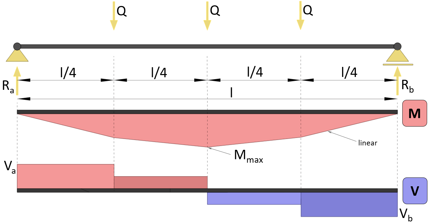
Simply Supported Beam вђ Moment Shear Force Formulas Du M 1.0 m = 0.3725 kn ⋅ 1.0 m = 0.3725 knm. in dependence of x and the point load q = 0.745kn a general formula for the bending moment of a simply supported beam for 0<x<l 2 can be formulated as: m x = 1 2 ⋅ q ⋅ x. you might have already come across the formula when we set x=l 2. Introduction notations relative to “shear and moment diagrams” e = modulus of elasticity, psi i = moment of inertia, in.4 l = span length of the bending member, ft. r = span length of the bending member, in. m = maximum bending moment, in. lbs. p = total concentrated load, lbs. r = reaction load at bearing point, lbs. v = shear force, lbs. The simply supported beam is one of the most simple structures. it features only two supports, one at each end. one is a pinned support and the other is a roller support. with this configuration, the beam is inhibited from any vertical movement at both ends whereas it is allowed to rotate freely. due to the roller support it is also allowed to. Simply supported beam with point force at a random position. the force is concentrated in a single point, anywhere across the beam span. in practice however, the force may be spread over a small area. in order to consider the force as concentrated, though, the dimensions of the application area should be substantially smaller than the beam span.

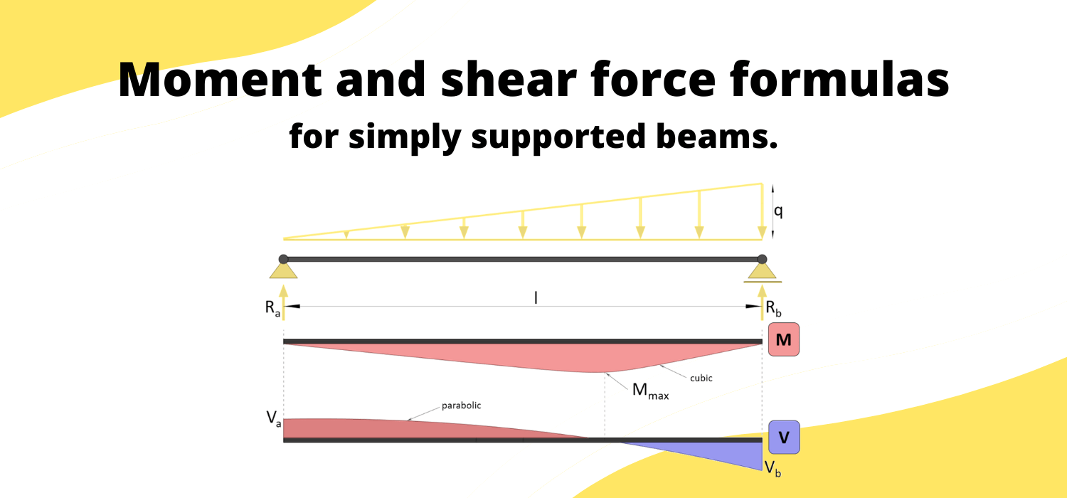
Moment And Shear Force Formulas For Simply Supported Beam The simply supported beam is one of the most simple structures. it features only two supports, one at each end. one is a pinned support and the other is a roller support. with this configuration, the beam is inhibited from any vertical movement at both ends whereas it is allowed to rotate freely. due to the roller support it is also allowed to. Simply supported beam with point force at a random position. the force is concentrated in a single point, anywhere across the beam span. in practice however, the force may be spread over a small area. in order to consider the force as concentrated, though, the dimensions of the application area should be substantially smaller than the beam span. The simply supported beam is in most cases a horizontal beam having a roller and a pinned support on the ends. the beam can take normal and shear forces, as well as bending moments. it can be seen from the picture that the pinned support (a) takes up. a vertical reaction force va and. a horizontal reaction force ha. 5.2 shear force and bending moment. when a statically determinate beam is cut across a section, one can find out the vertical shear force and the bending moment exerted by one free body on the other through the cut section so that both the free bodies are in equilibrium. this is as shown in fig. 5.3 for. fig.5.3 shear force and. p. bending moment.

Comments are closed.