Simple Pcb Circuit Diagram

Simple Circuit Diagram For Pcb 5. fire alarm project. objective: detect fire in a given area and warn using an alarm system. though simple in nature this circuit will help you to understand how real world electronics systems are built. this circuit is a basic one that senses smoke to detect fire and hence produce an alarm to warn people around. For this purpose, in this article, we will discuss some simple pcb electronic projects that you can make and practice on the pcb. so, to make these projects you can use any pcb software like orcad or protel. (1) battery voltage monitor. this simple circuit is made from the operational amplifier ic. the ic is operated as a comparator in this.

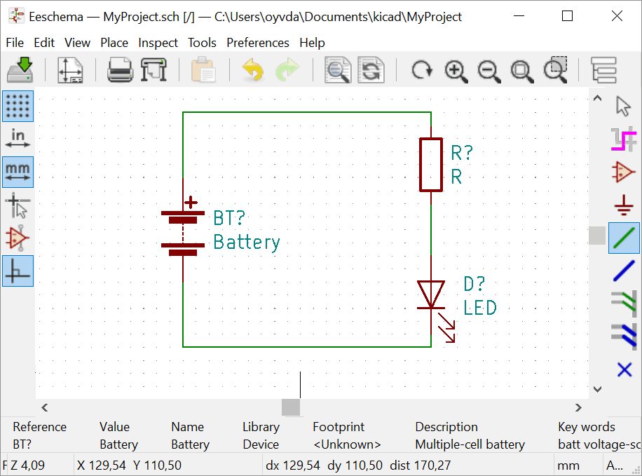
Simple Pcb Circuit Diagram Step 1: create or find a circuit diagram. before you start drawing wires and stuff, you need to know what circuit you want to build. so you need a circuit diagram. you can either find one that someone else has made, or you can design your own from scratch. i recommend starting with something simple. Printed circuit board is the most common name but may also be called "printed wiring boards" or "printed wiring cards". before the advent of the pcb circuits were constructed through a laborious process of point to point wiring. this led to frequent failures at wire junctions and short circuits when wire insulation began to age and crack. >. Pcb projects. pcb designing is a vital step in every product development cycle. the below list provides you with a collection of diy pcb projects which can be used to develop pcb designing skills. each project consists of a useful practical circuit that is demonstrated with a neatly fabricated pcb. the design details including the gerber file. To start drawing your board layout (assuming you’re still in the schematics editor), click on the toolbar button that says run pcbnew to layout printed circuit board, as shown in image 10.1. or go to the tools menu and select open pcb editor. this opens up the board editor window. image 10.1.

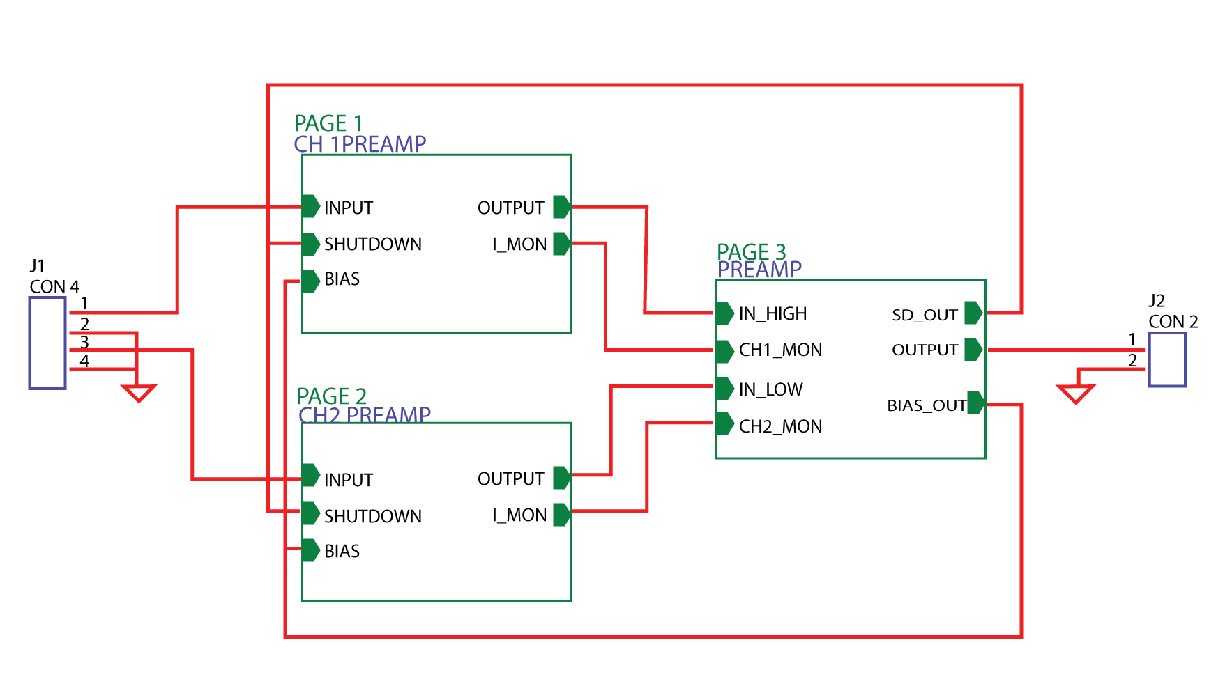
Pcb Design How To Create A Printed Circuit Board From Scratch Pcb projects. pcb designing is a vital step in every product development cycle. the below list provides you with a collection of diy pcb projects which can be used to develop pcb designing skills. each project consists of a useful practical circuit that is demonstrated with a neatly fabricated pcb. the design details including the gerber file. To start drawing your board layout (assuming you’re still in the schematics editor), click on the toolbar button that says run pcbnew to layout printed circuit board, as shown in image 10.1. or go to the tools menu and select open pcb editor. this opens up the board editor window. image 10.1. Step 2: create a blank pcb layout. after you’ve created your schematic, for the next pcb design step you’ll need to use the schematic capture tool in altium designer to import components into a blank pcb layout. first, create a blank printed circuit board document which will generate a pcbdoc file. 9. illustrate the signal flow path using a hierarchical schematic design. if the design is complex and contains many modules, a hierarchical design is preferred. the hierarchical schematic clearly displays the signal flow from one module to another, as shown below. a detailed view of each module can be accessed by clicking on the respective.

Comments are closed.