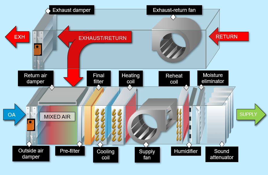
Schematic Diagram Of Air Handling Unit

Schematic Diagram Of Air Handling Unit The air handling unit schematic diagram is a detailed representation of the various components that make up the unit. it illustrates the flow of air through the system, highlighting the key elements such as the fan, filters, heating and cooling coils, and dampers. by examining this diagram, hvac professionals can gain a deeper understanding of. Diagram, parts & working. 31 jul 2021 by electrical workbook. the air handling unit (ahu) unit consists of: air distribution system: it includes various inlets for re circulated air and ducts for the supply air. duct system: it includes the return duct, supply duct and air conditioning apparatus including dampers, filters, coils or air washer.

Air Handling Unit Maintenance That Gets Results Rasmech An air handling unit (ahu) is a key component of a heating, ventilation, and air conditioning (hvac) system. it is responsible for distributing conditioned air throughout a building. an ahu consists of several important components, each playing a specific role in the overall operation of the unit. 1. filters. The air handling unit (ahu) schematic diagram is a technical representation of the components and connections involved in the operation of an ahu. it provides a visual overview of how the ahu functions, helping engineers, technicians, and operators understand and troubleshoot the system. at the heart of the ahu schematic diagram is the blower. Air handling units, which usually have the acronym of a.h.u are found in medium to large commercial and industrial buildings. they are usually located in the basement, on the roof or on the floors of a building. ahu’s will serve a specified area or zone within a building such as the east side, or floors 1 – 10 or perhaps a single purpose. Figure 1 shows the schematic diagram of a typical ahu. the fresh air is mixed with the air through the recycled air damper, depend ing on the fresh air damper position (the fresh air damper.

Air Handling Unit Ahu And 10 Desire Working Principle Air handling units, which usually have the acronym of a.h.u are found in medium to large commercial and industrial buildings. they are usually located in the basement, on the roof or on the floors of a building. ahu’s will serve a specified area or zone within a building such as the east side, or floors 1 – 10 or perhaps a single purpose. Figure 1 shows the schematic diagram of a typical ahu. the fresh air is mixed with the air through the recycled air damper, depend ing on the fresh air damper position (the fresh air damper. 🟧 air handling unit schematic diagram [typical 2 pipe] the below shows a typical detail for the pipework configuration, with an explanation below. a two pipe [2] system is the most basic form of design and installation, and the unit will have two possible configurations. Ternal component of any ahu is the damper. this is multiple sheets of rotating metal that are used to. adjust the volume of air entering the ahu. they can op. n and close fully and also open partially.as well as controlling the volume of air, dampers are important when it comes to preventing the spread of fire, clo.

Comments are closed.