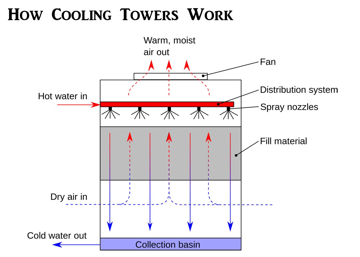
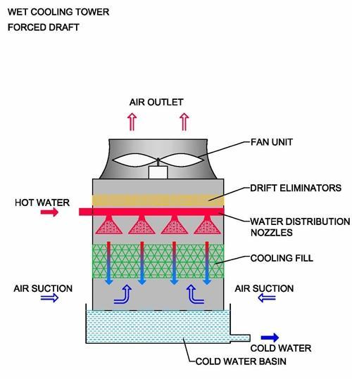
Schematic Diagram Of A Cooling Tower

Cooling Tower Piping Schematic Diagram Condenser water return pipework [1] the cooling tower return pipework is installed to transport the warm water from the condenser side of the water cooled chiller to the cooling tower, with the flow being provided by the condenser water pumps that are installed on the supply side of the tower [tower to chiller] to move the water around the system. The water is flashed to air as it passes throughout the cooling tower. the air has been pulled using a motor driven electrical "cooling tower fan". when the air and water come into the contact, a little amount of water dissipates, producing a cooling operation. and again the cold water is pumped back to the machine that incorporates heat or the.

Cooling Tower Diagram A Go To Guide To Learn About Their Function A cooling tower flow diagram is a visual representation of the flow of water and air in a cooling tower system. it provides a clear understanding of how the cooling tower operates and helps in identifying potential issues or inefficiencies in the system. there are several benefits of using a cooling tower flow diagram. The water is exposed to air as it flows throughout the cooling tower. the air is being pulled by an motor driven electric “cooling tower fan”. when the air and water come together, a small volume of water evaporates, creating an action of cooling. the colder water gets pumped back to the process equipment that absorbs heat or the condenser. Closed circuit towers. in these cooling towers, it passes the working fluid through heat exchangers upon which the clean water is sprayed and a fan induced draft applied. the performance of the closed circuit cooling tower is near to the wet cooling towers. wet cooling towers. the wet cooling towers operates on the principle of evaporative cooling. Counterflow cooling tower diagram difference between crossflow and counterflow cooling towers: in counterflow cooling tower system processes, the air vertically flows upwards, counter to the water flow in the fill media. due to the air flowing vertically, it's not possible to use the basin's gravity flow like in crossflow towers.
Schematic Drawing Showing The Basic Components Of A Cooling Tower Closed circuit towers. in these cooling towers, it passes the working fluid through heat exchangers upon which the clean water is sprayed and a fan induced draft applied. the performance of the closed circuit cooling tower is near to the wet cooling towers. wet cooling towers. the wet cooling towers operates on the principle of evaporative cooling. Counterflow cooling tower diagram difference between crossflow and counterflow cooling towers: in counterflow cooling tower system processes, the air vertically flows upwards, counter to the water flow in the fill media. due to the air flowing vertically, it's not possible to use the basin's gravity flow like in crossflow towers. Section 1 – evaporative cooling towers an evaporative cooling tower is a heat exchanger that transfers heat from circulating water to the atmosphere. warm water from the heat source is pumped to the top of the tower and then flow down through plastic or wooden shells. as it falls downward . cooling towers – m07 001 3. Cooling tower is a direct heat exchanger, through which heat of the water is transferred to the atmospheric air. the water is cooled up to the wet bulb temeperature of air (see figure 1). the rate of evaporation depends on the following factors. amount of water surface exposed. the direction of air flow.

Comments are closed.