Rs232 9 Pin Pinout 9 Pin Rs232 Pinout Explained Riset

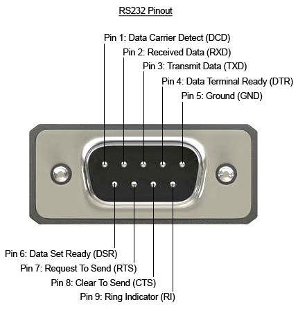
Rs232 9 Pin Pinout 9 Pin Rs232 Pinout Explainedођ The 9 pin serial connector, also known as a db9 connector, is a common interface used in computer and electronic systems. it facilitates the transmission of data between devices using a serial communication protocol. each pin in the connector serves a specific purpose, enabling the transfer of information such as data, control signals, and power. An rs232 pinout 9 pin cable features nine pins: 1. data carrier detect – after a data terminal is detected, a signal is sent to the data set that is going to be transmitted to the terminal. 2. received data – the data set receives the initial signal via the receive data line (rxd). 3.

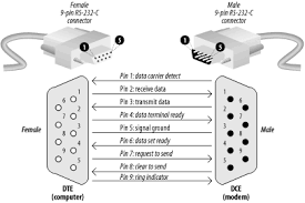
Rs232 9 Pin Pinout Stratus Engineering 25 pin serial pinout: pin 1: gnd − shield ground. pin 2: txd → transmitted data. carries data from the data terminal to the data set. pin 3: rxd ← received data. carries data from the data set to the data terminal. pin 4: rts → request to send. data terminal signals the data set to prepare for data transmission. A 9 pin serial cable, also known as a rs 232 cable or a db9 cable, is a type of cable commonly used to connect various devices and peripherals to a computer. it is primarily used for serial communication and data transfer between devices such as modems, printers, scanners, and gps receivers. the 9 pin serial cable features a male db9 connector. A serial pinout diagram is presented below. the rs232 protocol uses a 9 pin serial port that can have either male or female connectors. the most recent version of the protocol is known as rs232c. rs232c retains the features of rs232 but uses 25 pins rather than a 9 pin serial pinout. whether a db9 serial pinout or a 25 pin connection is used. The serial cable rs232 pin diagram is a visual representation of the wiring and connections between devices using an rs232 serial interface. rs232, or recommended standard 232, is a standard for serial communication that specifies the electrical, mechanical, and functional characteristics of the interface. the pin diagram shows the layout and.

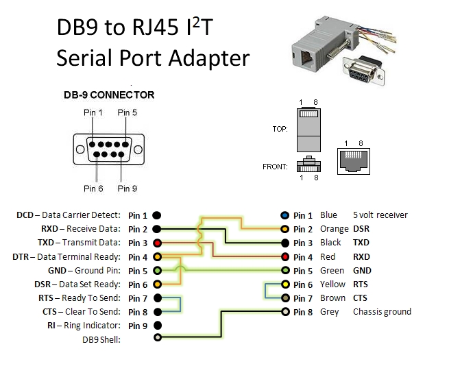
9 Pin Rs232 Pinout Qleroomatic A serial pinout diagram is presented below. the rs232 protocol uses a 9 pin serial port that can have either male or female connectors. the most recent version of the protocol is known as rs232c. rs232c retains the features of rs232 but uses 25 pins rather than a 9 pin serial pinout. whether a db9 serial pinout or a 25 pin connection is used. The serial cable rs232 pin diagram is a visual representation of the wiring and connections between devices using an rs232 serial interface. rs232, or recommended standard 232, is a standard for serial communication that specifies the electrical, mechanical, and functional characteristics of the interface. the pin diagram shows the layout and. Troubleshoot any issues by rechecking the wiring and pin assignments. by carefully following these guidelines, you can ensure a reliable and efficient setup for your serial communication needs. proper wiring and configuration are the cornerstones of effective data transfer in any serial communication system. common pin functions in rs232. This section provides an overview of how to interpret the 9 pin rs232 pinout for pcs using synonyms and without directly using the terms “rs232,” “pin,” or “pinout.” common uses and applications of rs232 in pc connectivity. rs232, known for its robust serial communication capabilities, plays a pivotal role in establishing reliable.

Comments are closed.