Rlc Series Circuit

Rlc Parallel Rlc Series Circuit Resonance Your Electrical Guide A RLC circuit as the name implies consist of a Resistor, Capacitor and Inductor connected in series or parallel The circuit forms an Oscillator circuit which is very commonly used in Radio receivers Abstract: The transients associated with transient recovery voltage (TRV), reignition or restriking events can, in general, be related to either a series or parallel RLC circuit each with specific

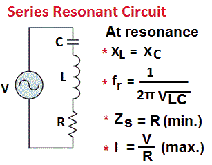
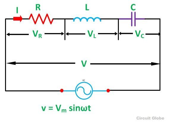
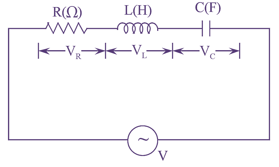
Rlc Series Circuit Electrical And Electronics Technology Degree Intended as a textbook for electronic circuit analysis or a reference for practicing engineers, the book uses a self-study format with hundreds of worked examples to master difficult mathematic topics Intended as a textbook for electronic circuit analysis or a reference for practicing engineers, the book uses a self-study format with hundreds of worked examples to master difficult mathematic topics You will study a series RLC circuit from both a time-domain and frequency-domain perspective in order to investigate topics such as: damping, overshoot, rise time, frequency of oscillation, settling Just to drive the point home, have a look at a basic series RLC circuit (I’m assuming you can make the leap of faith as to what the R represents) The series RLC circuit shown above can be

Rlc Circuit Phase Diagram You will study a series RLC circuit from both a time-domain and frequency-domain perspective in order to investigate topics such as: damping, overshoot, rise time, frequency of oscillation, settling Just to drive the point home, have a look at a basic series RLC circuit (I’m assuming you can make the leap of faith as to what the R represents) The series RLC circuit shown above can be This chapter explores the steady‐state frequency domain impedance of series and parallel RLC combinations, including intuition on the impedance, resonance, and circuit response minima and maxima The Figure 5 Parallel resonance circuit with a series resistance connected to a source The ALICE-Bode Plotter software can make generating frequency and phase response plots much easier Using the There are many, but for this post, I’m going to take you inside a Dickson charge pump This is Circuit VR because not only are we going to discuss the circuit, we’ll look at an LT Spice The supply voltage is shared between components in a series circuit, so the sum of the voltages across all of the components in a series circuit is equal to the supply voltage, \({V_s}\)

Phasor Diagram For Rlc Series Circuit This chapter explores the steady‐state frequency domain impedance of series and parallel RLC combinations, including intuition on the impedance, resonance, and circuit response minima and maxima The Figure 5 Parallel resonance circuit with a series resistance connected to a source The ALICE-Bode Plotter software can make generating frequency and phase response plots much easier Using the There are many, but for this post, I’m going to take you inside a Dickson charge pump This is Circuit VR because not only are we going to discuss the circuit, we’ll look at an LT Spice The supply voltage is shared between components in a series circuit, so the sum of the voltages across all of the components in a series circuit is equal to the supply voltage, \({V_s}\) All first-year students, including those who commute from home, are assigned to a Residential Learning Community The RLC system provides a distinct opportunity to connect and learn, both inside and

Comments are closed.