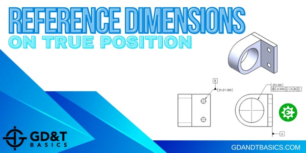
Reference Dimensions On True Position

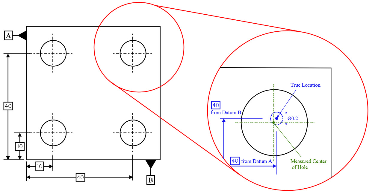
True Position Tolerance Chart Sometimes, we may use multiple datums to accurately locate the feature. we denote this reference point using basic dimensions. this true position acts as our reference to measure the deviation of the actual manufactured parts. the true position is usually set at the centre of the feature being toleranced. Reference dimensions on true position. by crystal bemis on june 17, 2024. in this question line video, jason answers the following question regarding reference dimensions on true position: if a diameter is reference () on the drawing, does that make the gd&t under the diameter callout reference as well? to answer this question, jason walks.

Using True Position Vs Coordinate Dimensions Youtube A reference dimension is just what it sounds like. it is a dimension shown for reference. in other words it is there for informational purposes only. they are not a requirement in any way. reference dimensions can be used to clarify other dimensions on a drawing. in some instances, they make a drawing easier to understand. True position = 2 x sqrt( 0.0015^2 0.0015^2) = 0.004243. we're off from the 0.0015 true position tolerance by almost 2x! even with half the differences, so x and y are within 0.00075" of the true center, the true position still works out to be 0.002121". true position can be tougher than it looks on first glance!. Basic dimensions are typically used within the gd&t framework to control the location or geometry of features. the best example of when basic dimensions are used is when specifying true position. take a look at this drawing below: the basic dimensions are those dimensions in the boxes – the 30 and the 15. they do have tolerances, though, as. Let’s walk through an example of how to use the true position calculator for inspecting position of an internal feature at regardless of feature size (rfs). in the drawing below, we have an aluminum channel with holes described by the feature control frame as having a position of .008 at rfs in reference to datums a, b, and c.

Reference Dimensions On True Position Gd T Basics Basic dimensions are typically used within the gd&t framework to control the location or geometry of features. the best example of when basic dimensions are used is when specifying true position. take a look at this drawing below: the basic dimensions are those dimensions in the boxes – the 30 and the 15. they do have tolerances, though, as. Let’s walk through an example of how to use the true position calculator for inspecting position of an internal feature at regardless of feature size (rfs). in the drawing below, we have an aluminum channel with holes described by the feature control frame as having a position of .008 at rfs in reference to datums a, b, and c. See paragraph 4.11.10. the new standard allows a datum reference to be called out in a feature control frame with only certain degrees of freedom being constrained. the specific degrees of freedom are given after the datum letter by noting x, y, z, u, v, or w. see paragraphs 4.22 and 4.23. Using basic dimensions ensures the highest accuracy of the finished product. what is basic and reference dimension? basic dimensions are numerical values used to define the theoretically exact size, profile true position, orientation, or location of a feature or datum target. reference dimensions are enclosed in parentheses and provide.

True Position Gd T Basics See paragraph 4.11.10. the new standard allows a datum reference to be called out in a feature control frame with only certain degrees of freedom being constrained. the specific degrees of freedom are given after the datum letter by noting x, y, z, u, v, or w. see paragraphs 4.22 and 4.23. Using basic dimensions ensures the highest accuracy of the finished product. what is basic and reference dimension? basic dimensions are numerical values used to define the theoretically exact size, profile true position, orientation, or location of a feature or datum target. reference dimensions are enclosed in parentheses and provide.

Comments are closed.