Raspberry Pi Gpio Diagram

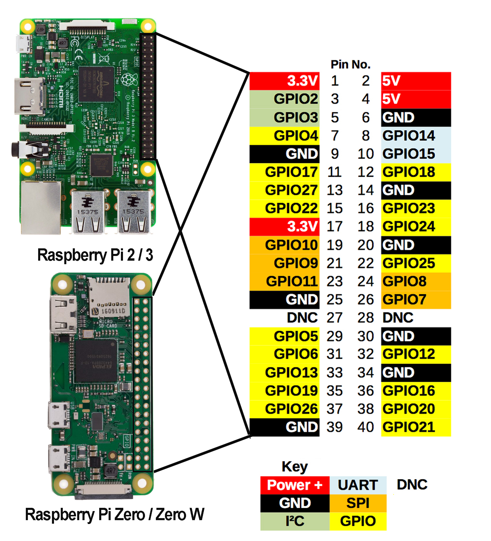
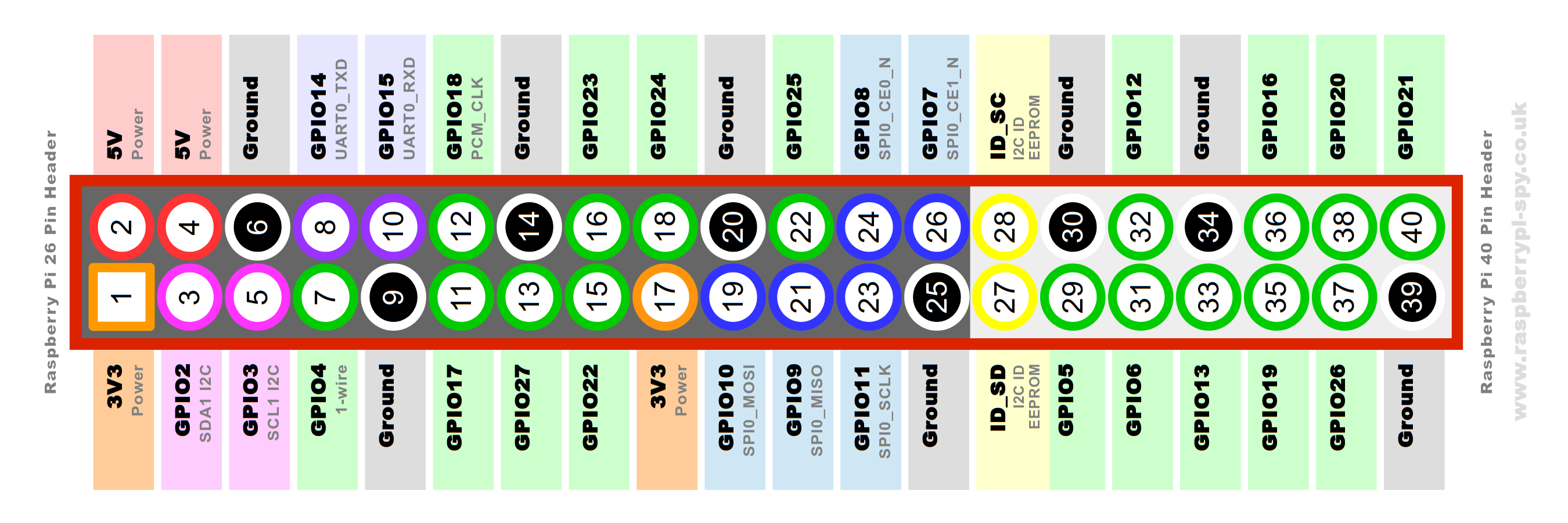
Raspberry Pi Gpio Diagram The raspberry pi gpio pinout guide. this gpio pinout is an interactive reference to the raspberry pi gpio pins, and a guide to the raspberry pi's gpio interfaces. pinout also includes hundreds of pinouts for raspberry pi add on boards, hats and phats. support pinout.xyz. if you love pinout, please help me fund new features and improvements:. Simplified diagram. when you take the raspberry pi board in front of you with the usb ports at the bottom, the gpio pin 1 is in the top left corner. number 2 is in the top right corner (not below), and from there it goes from left to right, and the next line, as if reading a book. also: i've tested hundreds of linux apps, here are the ones i.

Raspberry Pi Gpio Pinout Diagram This whitepaper assumes that the raspberry pi is running the raspberry pi operating system (os), and is fully up to date with the latest firmware and kernels. there are a number of otp values that can be used. to see a list of all the otp values, run the following command: $ vcgencmd otp dump. Before starting with the gpio pins practice, we need to do a few steps on the raspberry pi to make sure that everything is ready: start by updating your system. sudo apt update. sudo apt upgrade. install the rpi.gpio package (it should be pre installed on most versions) sudo apt install python3 rpi.gpio. In the diagram above, you can find the number after gpio. for example, on the raspberry pi 5, the pin below 3v3 is gpio2, so the number for this pin is 2 in bcm mode. a downside to bcm is that they have changed between versions (raspberry pi rev 1 vs raspberry pi rev 2) and may do so in the future. It allows you to establish communication with other microcontroller devices, sensors, or displays, for example. you can connect multiple i2c devices to the same pins as long they have a unique i2c address. the raspberry pi i2c pins are gpio 2 and gpio 3: sda: gpio 2. scl: gpio 3.

Raspberry Pi 4 Gpio Pin Diagram In the diagram above, you can find the number after gpio. for example, on the raspberry pi 5, the pin below 3v3 is gpio2, so the number for this pin is 2 in bcm mode. a downside to bcm is that they have changed between versions (raspberry pi rev 1 vs raspberry pi rev 2) and may do so in the future. It allows you to establish communication with other microcontroller devices, sensors, or displays, for example. you can connect multiple i2c devices to the same pins as long they have a unique i2c address. the raspberry pi i2c pins are gpio 2 and gpio 3: sda: gpio 2. scl: gpio 3. The raspberry pi offers up its gpio over a standard male header on the board. over the years the header has expanded from 26 pins to 40 pins while maintaining the original pinout. if you're coming to the raspberry pi as an arduino user, you're probably used to referencing pins with a single, unique number. The gpio enables you to switch devices on and off (output) or receive data from sensors and switches (input). what this really means is that you can connect the raspberry pi to everything from a smart mirror to a weather station, to an asset tracking robot that displays its coordinates on a web server.

Comments are closed.