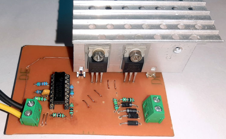
Pwm Inverter Using Ic Tl494 Circuit Homemade Circuit

Pwm Inverter Using Ic Tl494 Circuit Homemade Circuit Using tl494 for the design. the ic tl494 is a specialized pwm ic and is designed ideally to suit all types of circuits which require precise pwm based outputs. the chip has all the required features in built for generating accurate pwms which become customizable as per the users application specs. here i have explained a versatile pwm based. Inverter ic tl494. now before building the circuit based upon the tl494 pwm controller, let's learn how the pwm controller tl494 works. the tl494 ic has 8 functional blocks, which are shown and described below. 1. 5 v reference regulator. the 5v internal reference regulator output is the ref pin, which is pin 14 of the ic.

Pwm Inverter Using Ic Tl494 Circuit Homemade Circuit Inverter ic tl494. before constructing the circuit using the tl494 pwm controller, let's understand how the tl494 works. the tl494 ic comprises 8 functional blocks, outlined below: 5 v reference regulator: the ref pin (pin 14) provides a stable supply for internal circuitry, including the pulse steering flip flop, oscillator, dead time control. To make a stream lined ic tl494 pwm modified sine wave inverter, the iron core transformer could be swapped with a ferrite core transformer. the winding particulars for the same could possibly be noticed below: by means of super enamelled copper wire: primary: wind 5 x 5 turns center tap, choosing 4 mm (2 2 mm strands wrapped in parallel). Inverter ic tl494. before constructing the circuit using the tl494 pwm controller, let's understand how the tl494 works. the tl494 ic comprises 8 functional blocks, outlined below: 5 v reference regulator: the ref pin (pin 14) provides a stable supply for internal circuitry, including the pulse steering flip flop, oscillator, dead time control. Solar inverter using sg3525; introduction to tl494 pwm control ic. it is a complete pwm control ic. it can be used in single end operation as well as in push pull configuration. it also provides variable dead time which provides a maximum range of pwm. it has all the functions required to design a power supply circuit. block diagram of tl494 is.

Pwm Inverter Using Ic Tl494 Circuit Homemade Circuit Projects вђ Artofit Inverter ic tl494. before constructing the circuit using the tl494 pwm controller, let's understand how the tl494 works. the tl494 ic comprises 8 functional blocks, outlined below: 5 v reference regulator: the ref pin (pin 14) provides a stable supply for internal circuitry, including the pulse steering flip flop, oscillator, dead time control. Solar inverter using sg3525; introduction to tl494 pwm control ic. it is a complete pwm control ic. it can be used in single end operation as well as in push pull configuration. it also provides variable dead time which provides a maximum range of pwm. it has all the functions required to design a power supply circuit. block diagram of tl494 is. Tl494 bass and treble geek circuits. tl494 class d amplifier diyaudio. dc to converter circuit tl494 12v 30v adjule electronics projects circuits. pwm inverter using ic tl494 circuit homemade projects. tl494 datasheet pinout application circuits homemade circuit projects. 300w power inverter using tl494 with feedback soldering mind. 2 inverter ic tl494. an inverter is a circuit that converts direct current (dc) to alternating current (ac ). a pwm inverter is a type of circuit that uses modified square waves to simulate the effects of alternating current (ac), which is suitable for powering most of your household appliances. i say most of because there generally exist two.

Pwm Inverter Using Ic Tl494 Circuit Homemade Circuit Tl494 bass and treble geek circuits. tl494 class d amplifier diyaudio. dc to converter circuit tl494 12v 30v adjule electronics projects circuits. pwm inverter using ic tl494 circuit homemade projects. tl494 datasheet pinout application circuits homemade circuit projects. 300w power inverter using tl494 with feedback soldering mind. 2 inverter ic tl494. an inverter is a circuit that converts direct current (dc) to alternating current (ac ). a pwm inverter is a type of circuit that uses modified square waves to simulate the effects of alternating current (ac), which is suitable for powering most of your household appliances. i say most of because there generally exist two.

Comments are closed.