Peltier Module Circuit Diagram Circuit Diagram

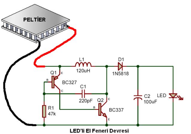
Peltier Module Circuit Diagram In a nutshell, a peltier module circuit diagram is a visual guide showing how electrical current flows into and out of the peltier module. it provides an easy to follow reference for installing and connecting the module, as well as the proper voltage and resistance settings. the diagram also allows users to see the relationship between the. 2 definition of peltier efficiency. this section gives an overview about the performance that can be reached using a reasonable amount of power. for this test, a 17.9 w, 3.9 a, 7.6 v, 30 mm x 15 mm et 063 10 13 peltier module is used. the performances can be defined by the difference of temperature between the ambient temperature and the cold.

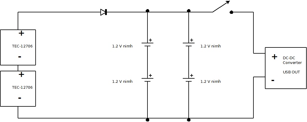
Peltier Module Circuit Diagram Circuit Diagram Figure 2: peltier module system design with constant voltage. however, in other applications, peltier modules are implemented to maintain an object at. controlled temperature. these designs utilize a thermal sensor, such as a thermocouple, solid state temperature sensor, or an infrared sensor to monitor the temperature of the object. Step 4: arduino setup: connecting the peltier unit. put the peltier module between two metal plates. the module should be placed in between the two plates to guide the heat away from the module. also, a bit of thermal paste should be used between the module and metal plates. This tec1 12706 module and the peltier effect makes the perfect diy cooler! this instructable is a step by step tutorial showing you how to make your homemade cooler. this diy fridge uses the peltier effect, which is the presence of heating or cooling at an electrified junction of two different conductors. The simple construction of a simple peltier refrigerator circuit shown in the figure demonstrates the above discussed set up where two such devices are appropriately fixed with aluminum plates for radiating different degrees of temperatures from their relevant sides. the plates responsible for generating the cooling effects must be trapped.

Peltier Module Circuit Diagram This tec1 12706 module and the peltier effect makes the perfect diy cooler! this instructable is a step by step tutorial showing you how to make your homemade cooler. this diy fridge uses the peltier effect, which is the presence of heating or cooling at an electrified junction of two different conductors. The simple construction of a simple peltier refrigerator circuit shown in the figure demonstrates the above discussed set up where two such devices are appropriately fixed with aluminum plates for radiating different degrees of temperatures from their relevant sides. the plates responsible for generating the cooling effects must be trapped. We want cooling to 5°c from an ambient temperature of 30°c. we also have available a peltier module of 71 elements (couples) and 6 ampere as imax. with the following proteus schematic we can estimate the thermal system performances: peltier cooling sysmem schematic. 1. i'm designing a tec circuit with a peltier element, lm35 as the sensor and arduino uno as the controller. i simulated it with proteus and to my knowledge it was working, i suppose. but when i tried to replicate the circuit on a bread board with the components, i had problems with pwm. can you guys please have a look at my circuit and advise.

Comments are closed.