Mppt Solar Charge Controller Wiring Diagram

60 Amp 96v Mppt Solar Charge Controller Inverter Advantages of using mppt charge controller. the advantages of incorporating an mppt controller into a solar power system are manifold. users typically experience an energy harvest increase of 20 30% compared to systems using pwm controllers. this boost in efficiency translates to more power available for use or storage. 100 30 wiring diagram. i brought the 100 30 mppt charge controller wanting a full wiring diagram picture how to wire it up as i'm not sure. solar panels to unit to battery and do i need to put a fuse or circuit breaker somewhere what size if i do any help would be great thanks i have 1 300w solar panel and two 12v batteries.

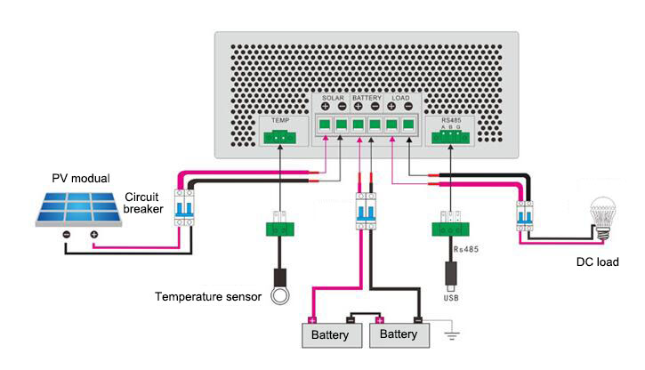
Mppt Solar Inverter Circuit Diagram Connecting solar panels to the input terminals. connect the positive ( ) and negative ( ) leads of the solar panels to the corresponding input terminals on the mppt charge controller. double check the polarity to avoid any reverse connections. 4. verifying polarity and secure connections. Smartsolar mppt 75 10 up to 100 20 fcc and industry canada compliance. 2. introduction. 2.1. battery voltage, pv voltage and current rating. 3. features. 3.1. automatic battery voltage detection. Install the solar charger in an enclosure or install the optional wirebox. 4.1. mounting. mount the solar charger vertically on a non flammable substrate, with the electrical terminals facing downwards. the dimension drawings chapter of this manual contains the dimension drawing of the solar charger, this drawing also indicates the mounting holes. The wiring diagram of the solar charge controller and dc load is shown as below. connect the pv panel module to the mppt charge controller the mppt solar charge controllers are suitable for 12v, 24v, and 48v off grid solar panel modules, and are also applied for the grid tie module of which the open voltage does not exceed the specified maximum.

Solar Panel Charge Controller Wiring Diagram Best Guide Install the solar charger in an enclosure or install the optional wirebox. 4.1. mounting. mount the solar charger vertically on a non flammable substrate, with the electrical terminals facing downwards. the dimension drawings chapter of this manual contains the dimension drawing of the solar charger, this drawing also indicates the mounting holes. The wiring diagram of the solar charge controller and dc load is shown as below. connect the pv panel module to the mppt charge controller the mppt solar charge controllers are suitable for 12v, 24v, and 48v off grid solar panel modules, and are also applied for the grid tie module of which the open voltage does not exceed the specified maximum. 2. appearance and wiring diagram 2) external view: 1) model identification: dms 40 c maximum load power product series model code, all in one single string step up constant current mppt charge controller 3) wiring diagram: mppt technology, providing a tracking efficiency of up to 99.5% and a charge conversion efficiency of up to 96%. Contact. the controller will manage the inverter's start or stop. if the lithium battery fails, it can protect the controller from being damaged because of the over current by preventing the controller from directly starting the inverter. (6) the controller is designed with a common negative polarity. the negative polarity of the pv and the.

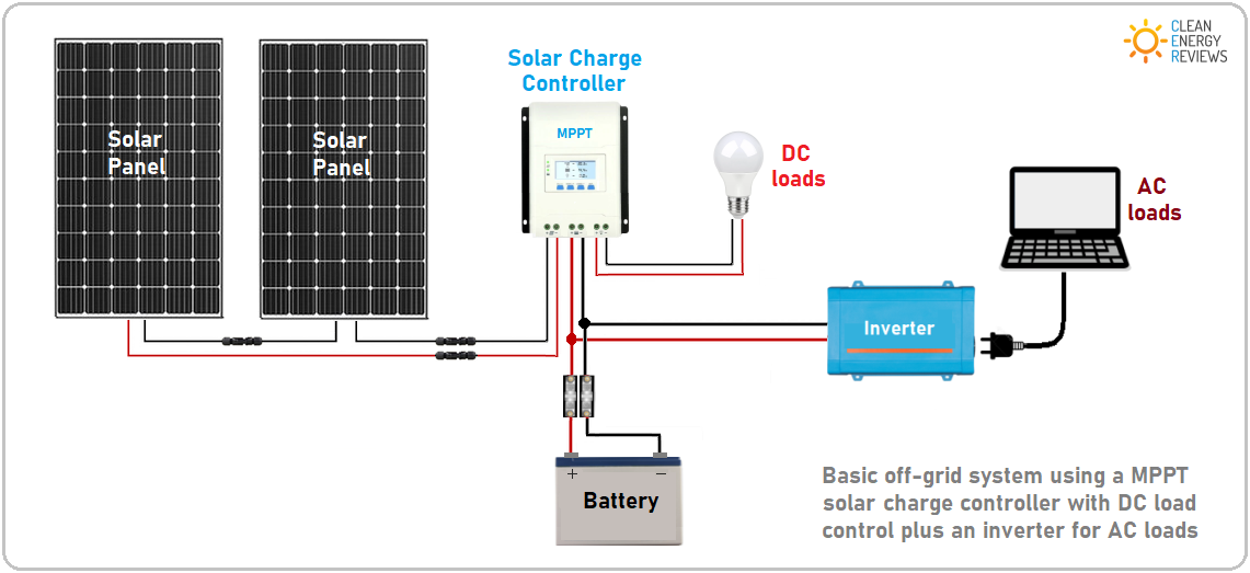
Mppt Solar Charge Controllers Explained вђ Clean Energy Reviews 2. appearance and wiring diagram 2) external view: 1) model identification: dms 40 c maximum load power product series model code, all in one single string step up constant current mppt charge controller 3) wiring diagram: mppt technology, providing a tracking efficiency of up to 99.5% and a charge conversion efficiency of up to 96%. Contact. the controller will manage the inverter's start or stop. if the lithium battery fails, it can protect the controller from being damaged because of the over current by preventing the controller from directly starting the inverter. (6) the controller is designed with a common negative polarity. the negative polarity of the pv and the.

Comments are closed.