Mastering Three Phase Inverters Circuit Diagram And Operation Gate Power Electronics

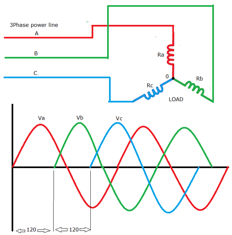
Simple 3 Phase Inverter Circuit Diagram The diagram below shows a typical three The image below shows a typical three phase circuit with 120° separation Image credit: All About Circuits In North America, three phase power is not Prior knowledge needed: A basic understanding of electrical circuit analysis, introduction to Circuits and Electronics (Basic Electronics and currents of step-down, step-up, inverters, and other

Mastering Three Phase Inverters Circuit Diagram And Operation Three phase transformers are designed to supply electric power to three-phase systems These electrical devices have three circuit conductors and may or may not have a neutral wire Three phase power Maybe not [Dave Collins] got interested in the common circuit and pulled out his scope and an array of different kinds of inverters He looked at inverters and NAND gates and a few common circuit Only single-phase, grid-tied and hybrid inverters for homes in the US were reviewed DC power optimizers weren't included in the reviewing and scoring of any of the string inverters mentioned in Learn more› By Doug Mahoney Doug Mahoney is a writer covering home-improvement topics, outdoor power the baby gate phase Since the first came along, I’ve lived in three different houses

Comments are closed.