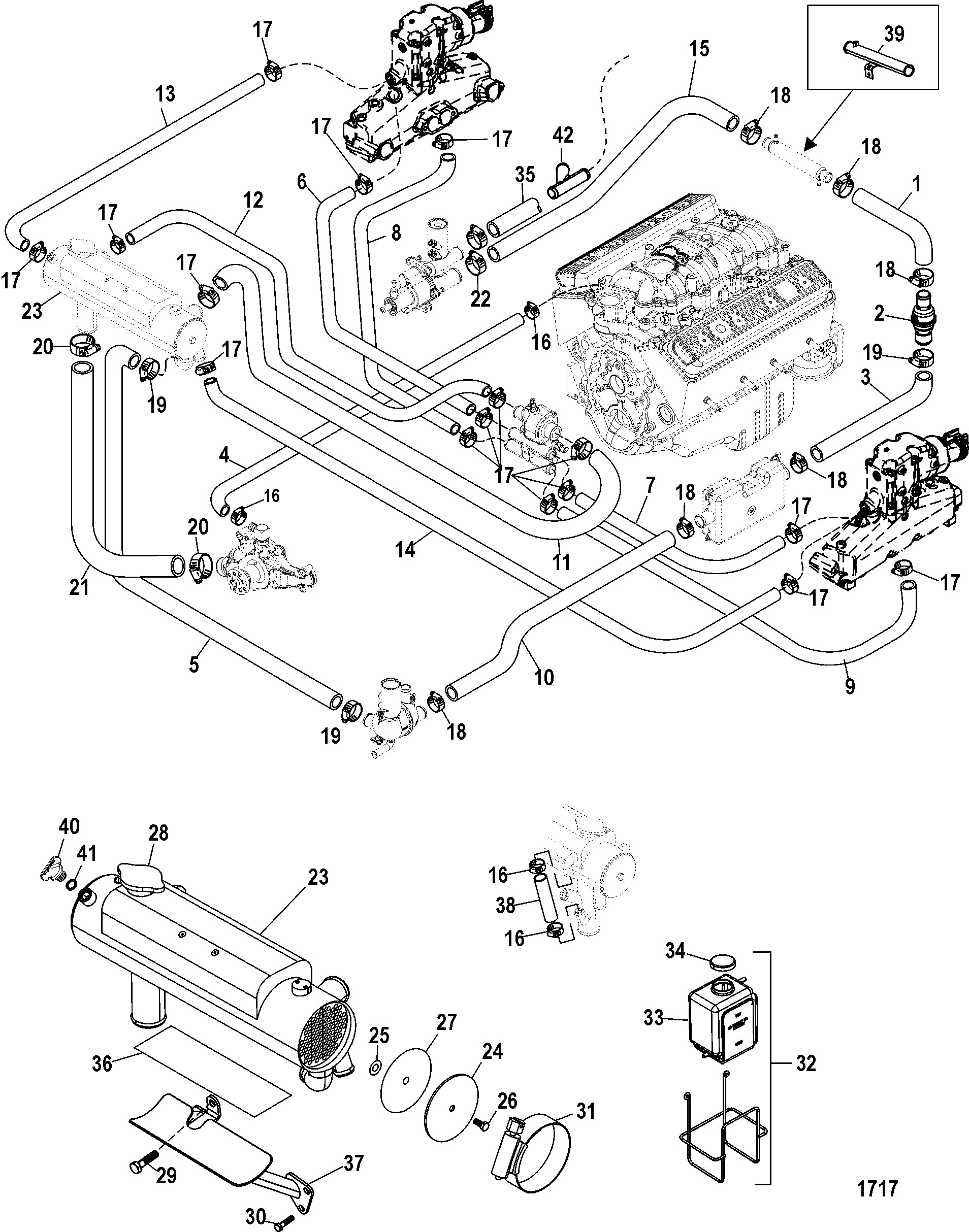
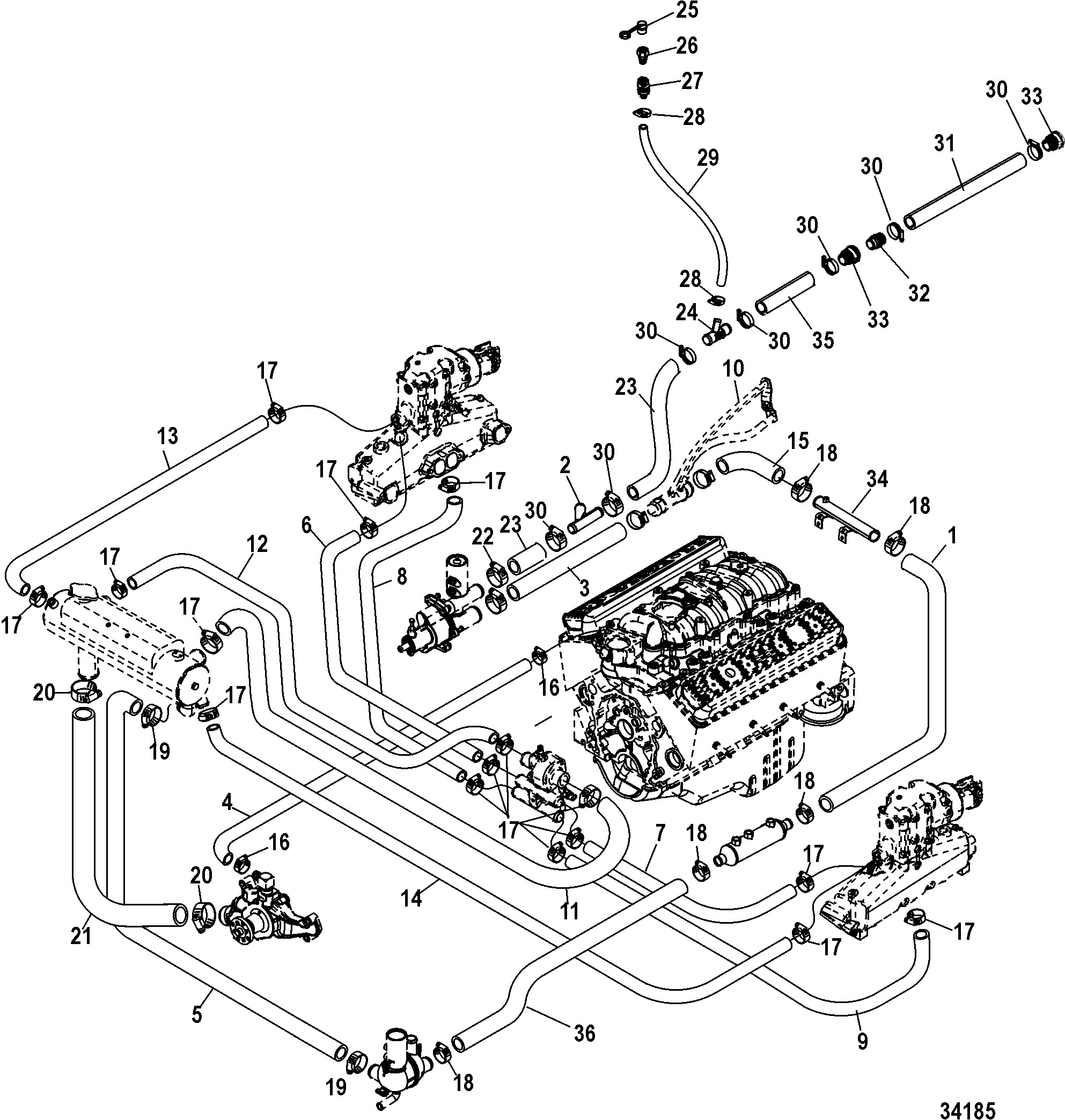
Marine Engine Cooling System Diagram Wiring Diagram Schemas 877
Marine Engine Cooling System Diagram Wiring Diagram Schemas 877 Tweet. #3. 07 14 2022, 04:25 pm. while you are waiting on the diagram, try a couple of primary steps. the first 2 steps help eliminate air infiltration into the system that leads to overheating. remove, clean and inspect strainer for cracks. put vaseline on the rubber gasket and re install. A volvo penta raw water cooling system is an essential component of a marine engine, ensuring optimal performance and durability. this system works by drawing in water from the surrounding environment, circulating it through the engine, and then releasing it back into the water. the raw water cooling system starts with a water intake located on.

Marine Engine Cooling System Diagram My Wiring Diagram Rine power part.this manual also contains many commonly used parts for the 350 cid pr. vortec en gine. most parts fit both the 5.7l vortec and th. 350 cid engine.as a reference, marine power utilizes 5.7v when referring to the vortec engine and 350 when referring to the p. The cooling system in a mercruiser engine consists of several components, including the water pump, thermostat, heat exchanger, and circulating pump. understanding how these components work together to ensure proper coolant flow is crucial for troubleshooting and diagnosing potential problems. the flow of coolant begins with the water pump. Remove the fuel fi lter element from the suspended pump by gripping the fuel pump with one hand, and pulling the fi lter element downward with the other hand. 7. visually inspect all internal components, i.e. hoses, wires, etc. 8. push on new fi lter element (part number rp080026) over the electric fuel pump. The italian company nanni diesel was created in 1952 in milan for the production of marine engines based on land diesel engines. initially, the company adapted only farymann models for the water area, but later, increasing its production capacity and engineering staff, nanni diesel significantly expanded the range of its partners.

Marine Engine Cooling System Diagram My Wiring Diagram Remove the fuel fi lter element from the suspended pump by gripping the fuel pump with one hand, and pulling the fi lter element downward with the other hand. 7. visually inspect all internal components, i.e. hoses, wires, etc. 8. push on new fi lter element (part number rp080026) over the electric fuel pump. The italian company nanni diesel was created in 1952 in milan for the production of marine engines based on land diesel engines. initially, the company adapted only farymann models for the water area, but later, increasing its production capacity and engineering staff, nanni diesel significantly expanded the range of its partners. Page 32: maintaining the engine cooling system maintaining the engine cooling sure (10 psi) is essential for optimal engine cooling and minimal coolant loss. system refer to table 4 1 for scheduled maintenance. coolant hoses cooling system overview check for and replace hoses that leak or are dam the engine is cooled by a pressurized, closed. A particular exhaust manifold is designed for a particular waterflow path and exhaust elbow. on many raw water cooled systems, water is pumped into the front of the exhaust manifold and exits out the back into the elbow riser. chris had a sophisticated system called "thermo electron" as i recall. in that system they carefully managed water flow.

Comments are closed.