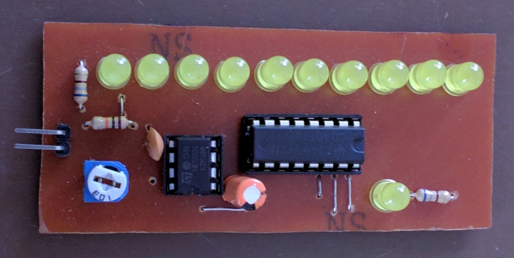
Led Chaser Using Ic 555 4017 Ic On Breadboard Led Chase

Led Chaser Using 4017 Counter And 555 Timer A tutorial on how to make an led chaser circuit sequential led flasher using 555 timer ic, cd4017 ic on a breadboard. working of the circuit is explained a. This pulsing output from the 555 timer is connected to the clock input of 4017 ic (a decade counter). it has 10 output pins and we have connected an led to each output. by default, the first output pin is on high and the rest are off. each time the clock input pin of 4017 ic detects a rise in voltage (from low to high), it turns off the current.

Led Chaser Circuit Diagram Using Ic 555 And Cd 4017 Vrogue Co Circuit diagram. led chaser using 4017 counter and 555 timer. you can see that the 555 timer wired as an astable multivibrator and its output is connected to the clock input of 4017 counter ic. the output frequency of the 555 timer is determined by the resistors r1, rv1 and capacitor c1. vcc (8 th pin) and gnd (1 st pin) is connected to the. The 555 timer ic is connected in astable mode to produce a trigger pulse with a specific time period. a variable resistor is included to adjust the output frequency of the 555 timer. a cd4017 counter ic is also incorporated in the circuit for controlling the leds. ten leds are connected to the q0 q9 pin (pin 3) via a 220 ohm resistor. The led will glow one by one per period and it will cycle repeats as running light. in circuit uses ic 555 as an oscillator pulse generator and ic 4017 to drive leds. parts used in this circuit are easily available in most of the local markets. table of contents. chaser circuit using ic 4017 ic 555. A video tutorial showing you how to construct a simple led chaser circuit on a breadboard using a 555 in astable mode and a 4017b as a decade counter.please.

How To Make Led Chaser Circuit With Only 4017 Ic Youtube The led will glow one by one per period and it will cycle repeats as running light. in circuit uses ic 555 as an oscillator pulse generator and ic 4017 to drive leds. parts used in this circuit are easily available in most of the local markets. table of contents. chaser circuit using ic 4017 ic 555. A video tutorial showing you how to construct a simple led chaser circuit on a breadboard using a 555 in astable mode and a 4017b as a decade counter.please. A tutorial on how to make a knight rider style led chaser circuit using 4017 ic 555 timer on breadboard along with detailed explanation on how the circuit. In an led chaser circuit, the 555 timer is configured as an astable oscillator, which means that it will generate a continuous stream of pulses. the frequency of the pulses can be adjusted by changing the values of the resistors and capacitors that are connected to the timer ic. the pulses generated by the 555 timer are then used to control a.

Led Chaser Circuit Using 555 Timer Cd 4017 Ic On Brea Vrogue Co A tutorial on how to make a knight rider style led chaser circuit using 4017 ic 555 timer on breadboard along with detailed explanation on how the circuit. In an led chaser circuit, the 555 timer is configured as an astable oscillator, which means that it will generate a continuous stream of pulses. the frequency of the pulses can be adjusted by changing the values of the resistors and capacitors that are connected to the timer ic. the pulses generated by the 555 timer are then used to control a.

Led Chaser With Only 4017 Youtube

Comments are closed.