Led Chaser Circuit Using 4017 And 555 Timer Ic Hackaday Io

Led Chaser Using 4017 Counter And 555 Timer You are about to report the project "led chaser circuit using 4017 and 555 timer ic", please tell us the reason. send message hello, i really like your project and i think i have skills to help you. 3. forward reverse chaser using 1 x ic4017. to get a forward reverse effect using one 4017 ic we need to connect 8 diodes to the circuit. the 1st and the 6th led will be directly connected to the ic4017. the leds at the far end will get signals from only one pin however the one in the middle will receive signals from 2 x pins and hence we need.

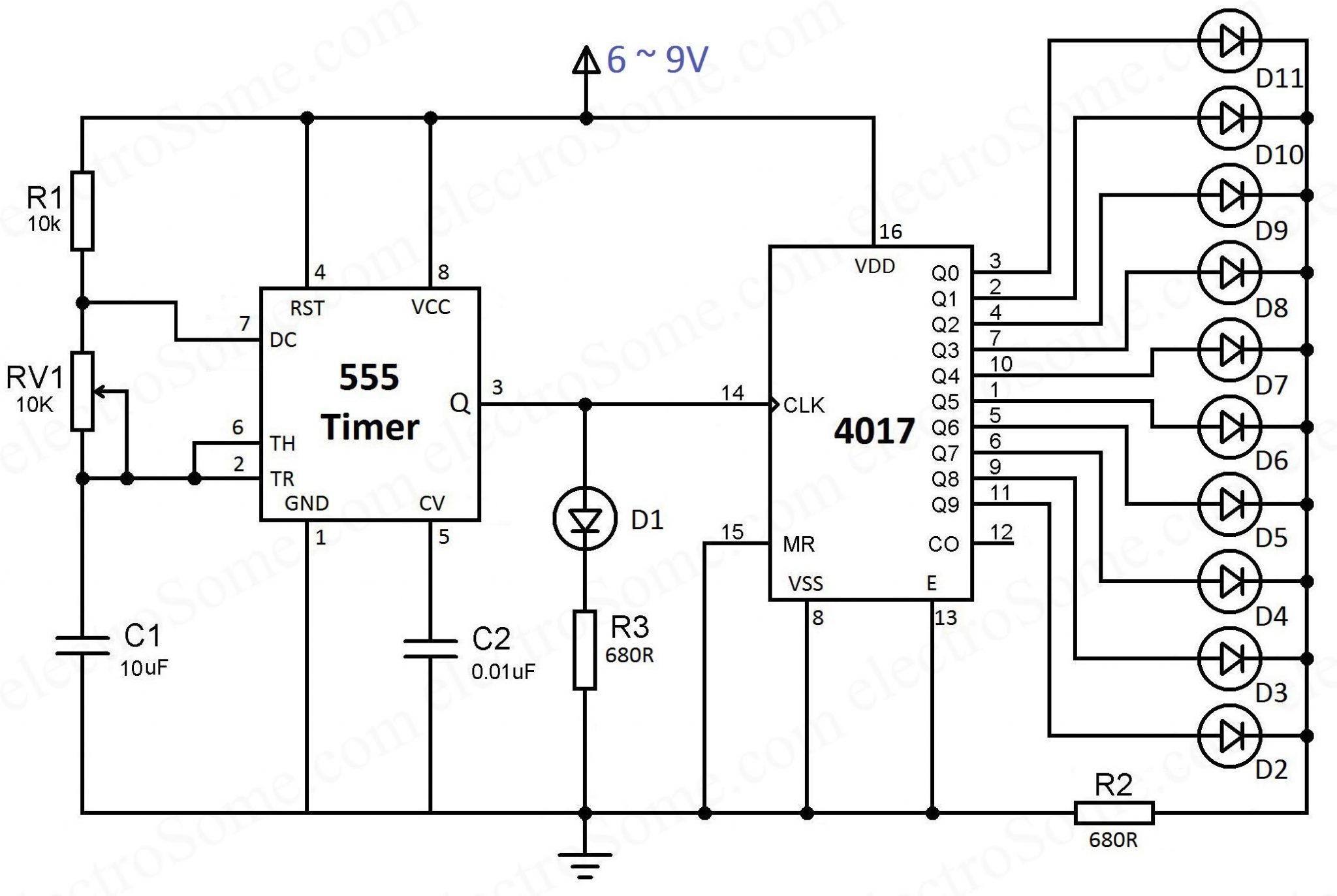
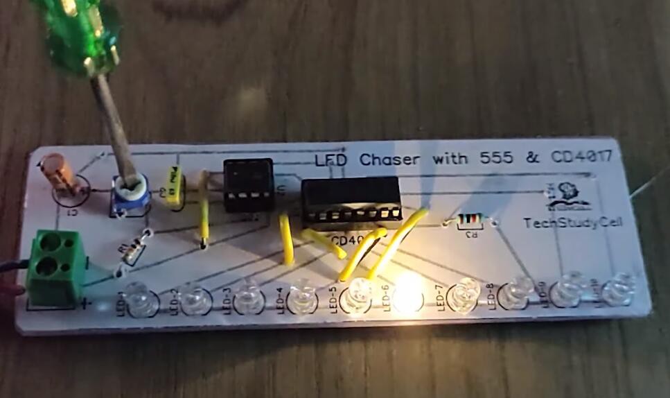
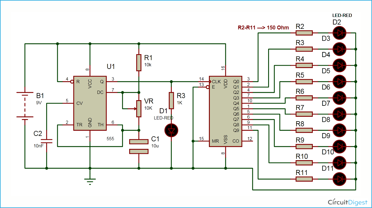
Led Chaser Circuit Using 4017 And 555 Timer Ic Hackaday Io Components required: 555 timer ic. cd 4017 ic. led lights x10. resistors: 470r, 1k, 47k. capacitor: 1uf. power supply: (5 15)v. [note: if you are using this circuit with a power source of 9v or above, use a 1k resistor in place of 470r.] before understanding how the circuit works, let me tell you that i am using custom made pcb to make this. The signal from the 555 ic clocks the 4017 decade counter. output of 555 timer ic on pin 3 is given as an input to 4017 ic through pin 14. whenever a pulse is received at the input of ic 4017, the counter increments the count and activates the corresponding output pin. this ic can count upto 10, so we have attached 10 leds to the circuit. In this 555 timer project, i have shown how to make an led chaser circuit using 4017 and 555 timer ic. the 555 ic will generate the clock pulse for the cd401. Circuit diagram. led chaser using 4017 counter and 555 timer. you can see that the 555 timer wired as an astable multivibrator and its output is connected to the clock input of 4017 counter ic. the output frequency of the 555 timer is determined by the resistors r1, rv1 and capacitor c1. vcc (8 th pin) and gnd (1 st pin) is connected to the.

Led Chaser Circuit Using 4017 And 555 Timer Ic Hackaday Io In this 555 timer project, i have shown how to make an led chaser circuit using 4017 and 555 timer ic. the 555 ic will generate the clock pulse for the cd401. Circuit diagram. led chaser using 4017 counter and 555 timer. you can see that the 555 timer wired as an astable multivibrator and its output is connected to the clock input of 4017 counter ic. the output frequency of the 555 timer is determined by the resistors r1, rv1 and capacitor c1. vcc (8 th pin) and gnd (1 st pin) is connected to the. A tutorial on how to make an led chaser circuit sequential led flasher using 555 timer ic, cd4017 ic on a breadboard. working of the circuit is explained a. Step 1: circuit diagram. construct the circuit as shown in the circuit diagram. for making the led chaser you require 555 timer & 4017 counter. the 555 timer is used to produce the clock pulses for the 4017. the 4017 is constructed in an astable configuration. when the clock pulse produced by the 555 timer is fed to the 4017, it starts counting.

Led Chaser Circuit Using 4017 And 555 Timer Ic Hackaday Io A tutorial on how to make an led chaser circuit sequential led flasher using 555 timer ic, cd4017 ic on a breadboard. working of the circuit is explained a. Step 1: circuit diagram. construct the circuit as shown in the circuit diagram. for making the led chaser you require 555 timer & 4017 counter. the 555 timer is used to produce the clock pulses for the 4017. the 4017 is constructed in an astable configuration. when the clock pulse produced by the 555 timer is fed to the 4017, it starts counting.

Led Chaser Circuit Diagram Using Ic 555 And Cd 4017

Comments are closed.