Led Chaser Circuit Diagram Using Ic 555 And Cd 4017

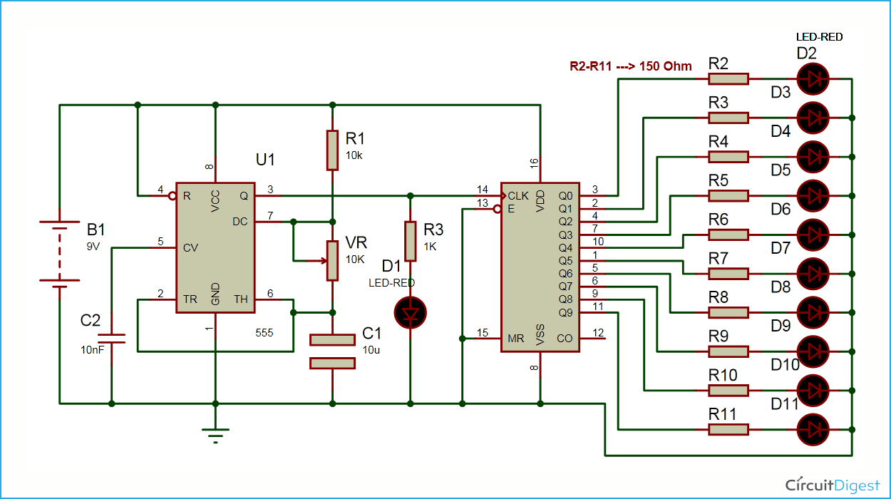
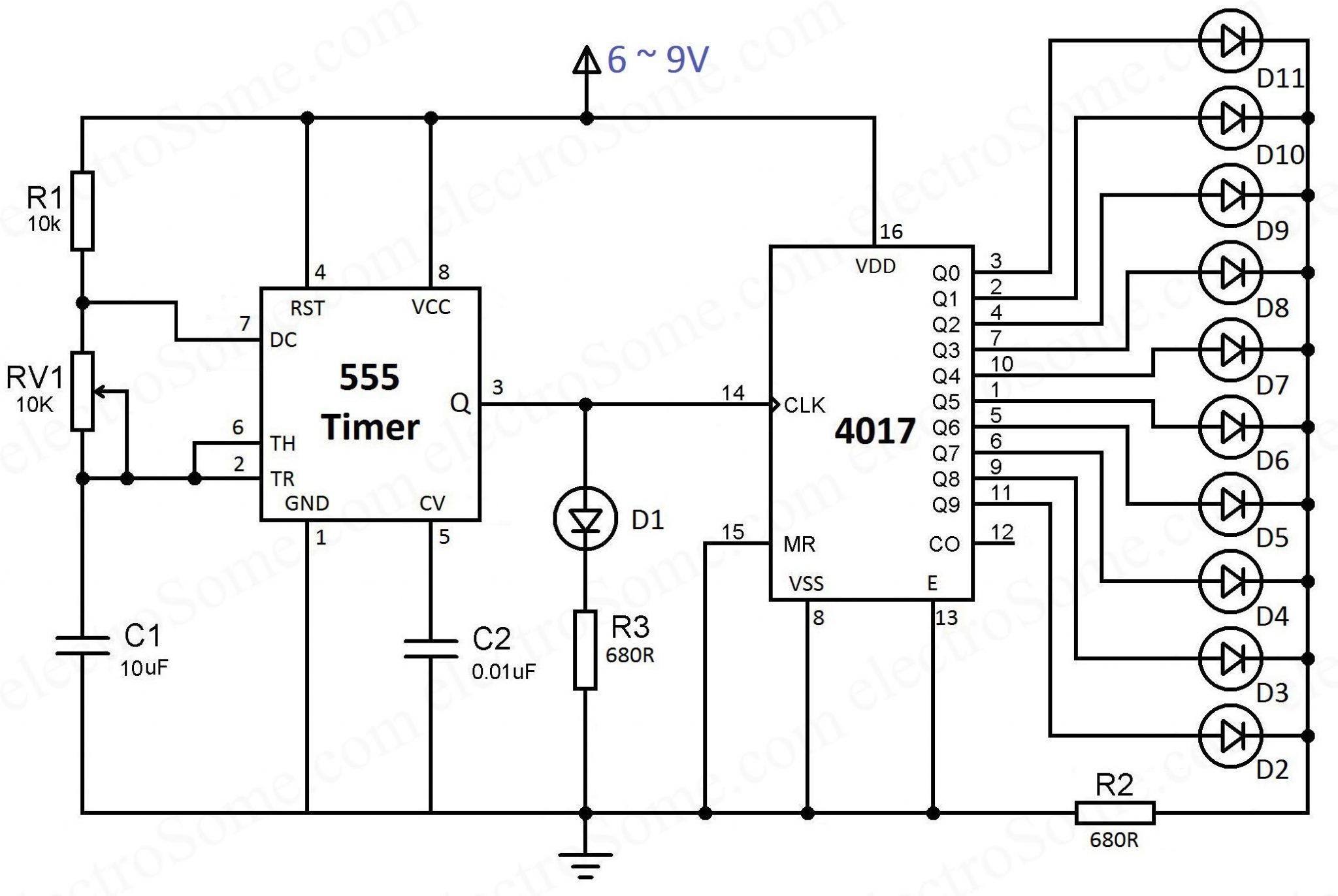
Led Chaser Circuit Diagram Using Ic 555 And Cd 4017 A cd4017 counter ic is also connected with this circuit for lighting leds. 10 red led’s are connected to q0 q9 pin (pin 3) through 150 ohm resistor. mr pin (pin 15), enable or clock inhbit pin (pin 13) is directly connected with ground and clock pin of counter directly connected with output pin of 555 timer. Circuit diagram. led chaser using 4017 counter and 555 timer. you can see that the 555 timer wired as an astable multivibrator and its output is connected to the clock input of 4017 counter ic. the output frequency of the 555 timer is determined by the resistors r1, rv1 and capacitor c1. vcc (8 th pin) and gnd (1 st pin) is connected to the.

Led Chaser Using 4017 Counter And 555 Timer The 555 timer ic is connected in astable mode to produce a trigger pulse with a specific time period. a variable resistor is included to adjust the output frequency of the 555 timer. a cd4017 counter ic is also incorporated in the circuit for controlling the leds. ten leds are connected to the q0 q9 pin (pin 3) via a 220 ohm resistor. Step 1: circuit diagram. construct the circuit as shown in the circuit diagram. for making the led chaser you require 555 timer & 4017 counter. the 555 timer is used to produce the clock pulses for the 4017. the 4017 is constructed in an astable configuration. when the clock pulse produced by the 555 timer is fed to the 4017, it starts counting. In this tutorial, we are going to demonstrate a led sequencer chaser using ne555 & cd4017. the purpose of this circuit is to turn the leds on one by one. cd4017 is a cmos counter ic, it gives 10 outputs according to the clock pulse it receives from the clock input (pin 14). ne 555 is a timer ic which is a very versatile ic widely used in. In an led chaser circuit, the 555 timer is configured as an astable oscillator, which means that it will generate a continuous stream of pulses. the frequency of the pulses can be adjusted by changing the values of the resistors and capacitors that are connected to the timer ic. the pulses generated by the 555 timer are then used to control a.

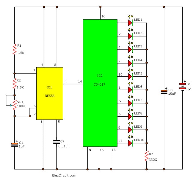
Led Chaser Circuit By Ic 4017 Ic 555 Eleccircuit In this tutorial, we are going to demonstrate a led sequencer chaser using ne555 & cd4017. the purpose of this circuit is to turn the leds on one by one. cd4017 is a cmos counter ic, it gives 10 outputs according to the clock pulse it receives from the clock input (pin 14). ne 555 is a timer ic which is a very versatile ic widely used in. In an led chaser circuit, the 555 timer is configured as an astable oscillator, which means that it will generate a continuous stream of pulses. the frequency of the pulses can be adjusted by changing the values of the resistors and capacitors that are connected to the timer ic. the pulses generated by the 555 timer are then used to control a. The ic 4017 is decade counter with 10 decoded outputs ic ic. circuit diagram of 2 way 12 led running lights using cd4017 and ne555. which its output glowing will slide down each position, by begin from output at 1 is pin 3, 2, 4, 7, 10, 1, 5, 6, 9 and 11 in sequence. when it to pin 11 the output light will back to pin 3 and continue to glow in. This pulsing output from the 555 timer is connected to the clock input of 4017 ic (a decade counter). it has 10 output pins and we have connected an led to each output. by default, the first output pin is on high and the rest are off. each time the clock input pin of 4017 ic detects a rise in voltage (from low to high), it turns off the current.

How To Make Led Chaser Circuit With Only 4017 Ic Youtube The ic 4017 is decade counter with 10 decoded outputs ic ic. circuit diagram of 2 way 12 led running lights using cd4017 and ne555. which its output glowing will slide down each position, by begin from output at 1 is pin 3, 2, 4, 7, 10, 1, 5, 6, 9 and 11 in sequence. when it to pin 11 the output light will back to pin 3 and continue to glow in. This pulsing output from the 555 timer is connected to the clock input of 4017 ic (a decade counter). it has 10 output pins and we have connected an led to each output. by default, the first output pin is on high and the rest are off. each time the clock input pin of 4017 ic detects a rise in voltage (from low to high), it turns off the current.

Circular Led Chaser Using 555 Timer Cd4017 Electronics Projects

Comments are closed.