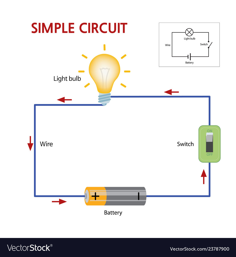
Labelled Diagram Of A Simple Electric Circuit Circuit Vrogue

Diagram Of A Simple Electric Circuit A basic electrical circuit (diagram) consists of three main components: the source, the load, and the conductors. the battery has two terminals. these terminals are connection points for the two conductors. one terminal is marked with a plus sign ( ) and the other a negative sign (–). these two markings are referred to as polarity markings. The labeled diagram of an electric circuit creates a simple and uniform structure for understanding the relationship between electrical components. this diagram makes it easy for both amateurs and professionals alike to develop a comprehensive schematic of their electrical systems. from electricians to engineers, this diagram is the foundation.

Simple Diagram Of Electric Circuit 1. use circuit symbols to construct schematic diagrams for the following circuits: a. a single cell, light bulb and switch are placed together in a circuit such that the switch can be opened and closed to turn the light bulb on. see answer. b. a three pack of d cells is placed in a circuit to power a flashlight bulb. In this step by step guide, we will outline the process of creating a basic circuit diagram. 1. identify the components. the first step is to identify the components that will be included in your circuit diagram. this may include items such as resistors, capacitors, leds, and power sources. An open circuit does not allow electrical current to flow. below is a basic set of symbols that you may find on circuit diagrams. schematic diagram of a simple circuit. note the parts of a simple circuit and the symbols that relate to them. a simple circuit has conductors, a switch, a load, and a power source. here are the functions of each part:. Draw arrows between the components to show the direction of the electricity flow and draw circles over each connection point. when labeling the connections, use terms such as “in”, “out”, and “through”. if appropriate, you can also include power sources.

Simple Electrical Circuit Diagrams An open circuit does not allow electrical current to flow. below is a basic set of symbols that you may find on circuit diagrams. schematic diagram of a simple circuit. note the parts of a simple circuit and the symbols that relate to them. a simple circuit has conductors, a switch, a load, and a power source. here are the functions of each part:. Draw arrows between the components to show the direction of the electricity flow and draw circles over each connection point. when labeling the connections, use terms such as “in”, “out”, and “through”. if appropriate, you can also include power sources. An electric circuit is a closed loop with a continuous flow of electric current from the power supply to the load. here are ten simple electric circuits commonly found around the home. electric circuits like ac lighting circuit, battery charging circuit, energy meter, switch circuit, air conditioning circuit, thermocouple circuit, dc lighting circuit, multimeter circuit, current transformer. Circuit diagram connections. circuit diagrams or schematic diagrams show electrical connections of wires or conductors by using a node as shown in the image below. a node is simply a filled circle or dot. when three or more lines touch each other or cross each other and a node is placed at the intersection, this represents the lines or wires.

Comments are closed.