Inverter Diagram Circuit

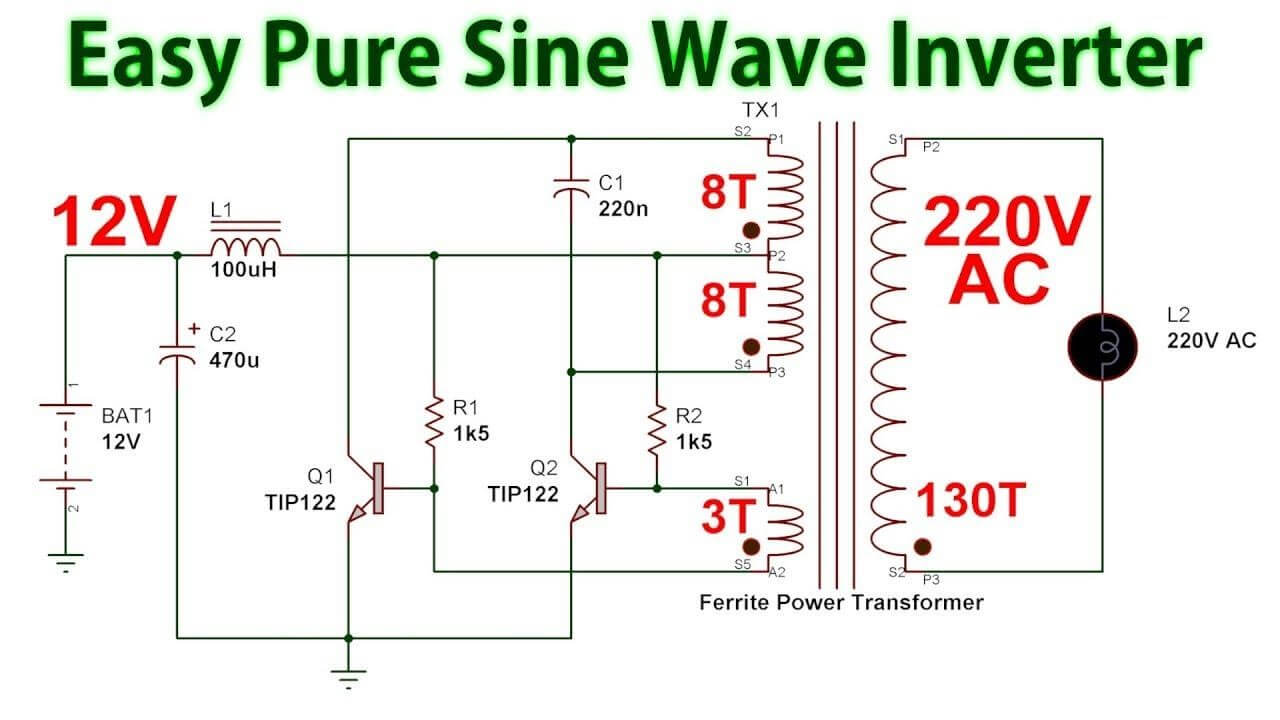
Inverter Circuit Diagram A Complete Tutorial Edrawmax 12v to 230v inverter circuit diagram. well your search for such a circuit ends here. the circuit of an inverter described here is perhaps the smallest as far its component count goes yet is powerful enough to fulfill most of your requirements. construction procedure. to begin with, first make sure to have proper heatsinks for the two 2n3055. Learn how to make an inverter circuit diagram with edrawmax software. find out the types, classification, and working of inverters, and see the logical symbol and steps to create a simple 100 watt inverter circuit.

Inverter Diagram Circuit Learn how to design and build a power inverter circuit that converts dc power into ac power. see the components, connections, and waveforms of a typical inverter circuit diagram. Learn how to design and use inverters to convert dc power to ac power for various applications. see the block diagram, pwm technique, h bridge circuit, and types of inverters. Learn how to create a power inverter that can convert a 12v battery into a 110v 220v ac current. see the block diagram, schematic, and oscilloscope waveforms of the circuit using a 555 timer and mosfet transistors. An inverter pcb diagram is a graphical representation of the components and connections on a printed circuit board (pcb) used in an inverter. the diagram provides a visual guide for technicians and engineers to understand the layout and functionality of the inverter. one of the key components in an inverter pcb diagram is the power input section.

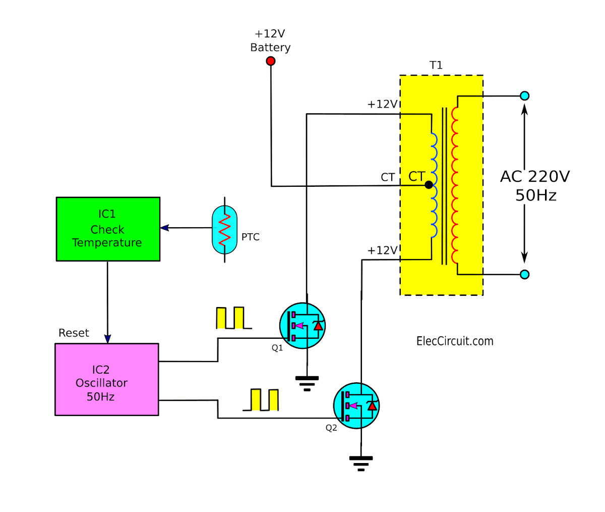
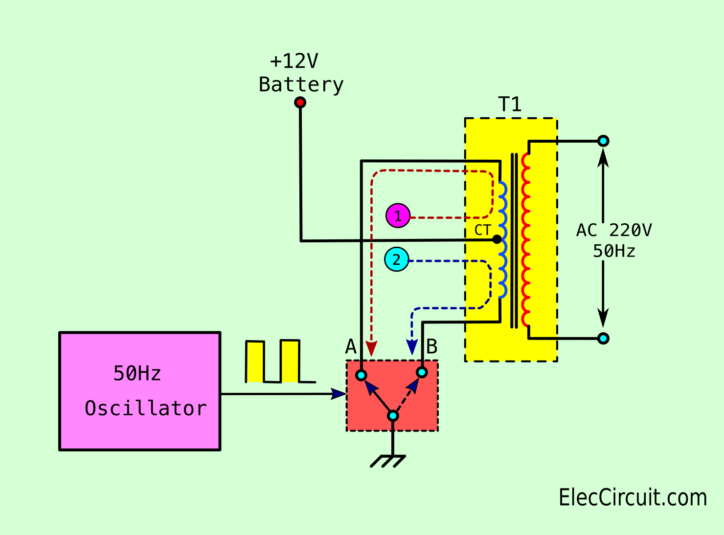
Power Inverter Schematic Circuit Diagrams Learn how to create a power inverter that can convert a 12v battery into a 110v 220v ac current. see the block diagram, schematic, and oscilloscope waveforms of the circuit using a 555 timer and mosfet transistors. An inverter pcb diagram is a graphical representation of the components and connections on a printed circuit board (pcb) used in an inverter. the diagram provides a visual guide for technicians and engineers to understand the layout and functionality of the inverter. one of the key components in an inverter pcb diagram is the power input section. An inverter circuit diagram is a graphical representation of the connections and components used in an inverter circuit. inverter circuits are electronic circuits that convert dc (direct current) power to ac (alternating current) power. they are commonly used in various applications such as power backup systems, solar power systems, and. Learn what is an inverter, how it works, and its different types such as single phase and three phase. see the circuit diagram of a push pull inverter with a center tap transformer and its applications in solar power systems, ups, and smps.

Simple Inverter Working Principle Eleccircuit An inverter circuit diagram is a graphical representation of the connections and components used in an inverter circuit. inverter circuits are electronic circuits that convert dc (direct current) power to ac (alternating current) power. they are commonly used in various applications such as power backup systems, solar power systems, and. Learn what is an inverter, how it works, and its different types such as single phase and three phase. see the circuit diagram of a push pull inverter with a center tap transformer and its applications in solar power systems, ups, and smps.

Comments are closed.