Introduction To Phasors Definition Examples Diagrams And 40 Off

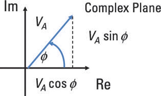
Introduction To Phasors Definition Examples Diagrams And 40 O A is the amplitude,; ω is the angular frequency (in radians per second),; t is time, and; ϕ is the phase angle (in radians).; phasors definition. a phasor is a complex number used to represent the magnitude and phase of a sinusoidal function, particularly in the context of alternating current (ac) electricity, signal processing, and wave mechanics. A phasor is a complex valued number that represents a real valued sinusoidal waveform. specifically, a phasor has the magnitude and phase of the sinusoid it represents. figure 1.5.1 and 1.5.2 show some examples of phasors and the associated sinusoids. it is important to note that a phasor by itself is not the signal.

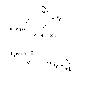
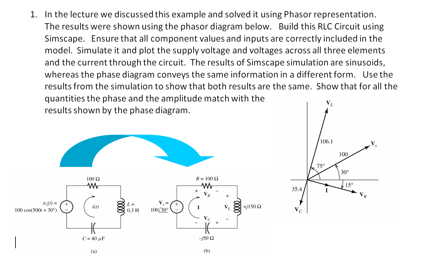
Introduction To Phasors Definition Examples Diagrams And 40 O Phasor diagram definition. a phasor is a scaled line whose length represents an ac quantity that has both magnitude (peak amplitude) and direction (phase) which is frozen at some point in time. a phasor diagram is used to show the phase relationships between two or more sine waves having the same frequency. The lengths of the phasors are proportional to the values of the voltage, ( v ) and the current, ( i ) at the instant in time that the phasor diagram is drawn. the current phasor lags the voltage phasor by the angle, Φ , as the two phasors rotate in an anticlockwise direction as stated earlier, therefore the angle, Φ is also measured in the same anticlockwise direction. This page titled 6.1: introduction to phasors is shared under a cc by 1.0 license and was authored, remixed, and or curated by bill wilson via source content that was edited to the style and standards of the libretexts platform. Phasor diagrams are graphical representations used to analyze and visualize the characteristics of alternating current (ac) circuits. they provide a way to simplify complex ac circuit calculations and understand the relationships between voltage, current, and impedance. a phasor diagram consists of vectors that represent the amplitude and phase.

Introduction To Phasors Definition Examples Diagrams And 40 O This page titled 6.1: introduction to phasors is shared under a cc by 1.0 license and was authored, remixed, and or curated by bill wilson via source content that was edited to the style and standards of the libretexts platform. Phasor diagrams are graphical representations used to analyze and visualize the characteristics of alternating current (ac) circuits. they provide a way to simplify complex ac circuit calculations and understand the relationships between voltage, current, and impedance. a phasor diagram consists of vectors that represent the amplitude and phase. 3 phase phasor diagram. a set of phasors is defined as the three complex cube roots of unity, graphically represented as unit magnitudes at angles of 0, 120 and 240 degrees in analysis of 3 phase ac power systems. balanced circuits can be simplified and unbalanced circuits can be treated as an algebraic combination of symmetrical circuits by. James kirtley. massachusetts institute of technology via mit opencourseware. phasors are not weapons. they are a handy geometric trick which help us understand the nature of sinusoidal steady state signals and systems. to start, consider the basis for complex exponential time notation, the function ejωt e j ω t.

Introduction To Phasors Definition Examples Diagrams And 40 O 3 phase phasor diagram. a set of phasors is defined as the three complex cube roots of unity, graphically represented as unit magnitudes at angles of 0, 120 and 240 degrees in analysis of 3 phase ac power systems. balanced circuits can be simplified and unbalanced circuits can be treated as an algebraic combination of symmetrical circuits by. James kirtley. massachusetts institute of technology via mit opencourseware. phasors are not weapons. they are a handy geometric trick which help us understand the nature of sinusoidal steady state signals and systems. to start, consider the basis for complex exponential time notation, the function ejωt e j ω t.

Comments are closed.