Introduction To Phasors Definition Examples Diagrams And 40 O

Introduction To Phasors Definition Examples Diagrams And 40 Off A is the amplitude,; ω is the angular frequency (in radians per second),; t is time, and; ϕ is the phase angle (in radians).; phasors definition. a phasor is a complex number used to represent the magnitude and phase of a sinusoidal function, particularly in the context of alternating current (ac) electricity, signal processing, and wave mechanics. A phasor is a complex valued number that represents a real valued sinusoidal waveform. specifically, a phasor has the magnitude and phase of the sinusoid it represents. figure 1.5.1 and 1.5.2 show some examples of phasors and the associated sinusoids. it is important to note that a phasor by itself is not the signal.

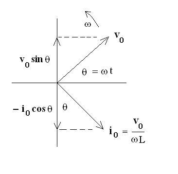
Introduction To Phasors Definition Examples Diagrams And 40 Off Ac theory. phasors and phasor algebra. may 21, 2024. by ravi teja. the ‘phasor’ is defined as “the complex number in the polar form with which we can analyze the circuit”. it is a vector quantity. in this vector representation we use cartesian plane. the y axis represents the magnitude and phase angle of the waveform in the form of. Introduction. in engineering and applied science, three test signals form the basis for our study of electrical and mechanical systems. the impulse is an idealized signal that models very short excitations (like current pulses, hammer blows, pile drives, and light flashes). the step is an idealized signal that models excitations that are. Phasor diagrams are graphical representations used to analyze and visualize the characteristics of alternating current (ac) circuits. they provide a way to simplify complex ac circuit calculations and understand the relationships between voltage, current, and impedance. a phasor diagram consists of vectors that represent the amplitude and phase. An example of series rlc circuit and respective phasor diagram for a specific ω. the arrows in the upper diagram are phasors, drawn in a phasor diagram ( complex plane without axis shown), which must not be confused with the arrows in the lower diagram, which are the reference polarity for the voltages and the reference direction for the current .

Comments are closed.