Introduction To Phasors

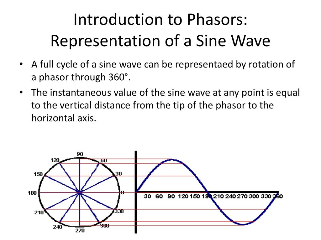
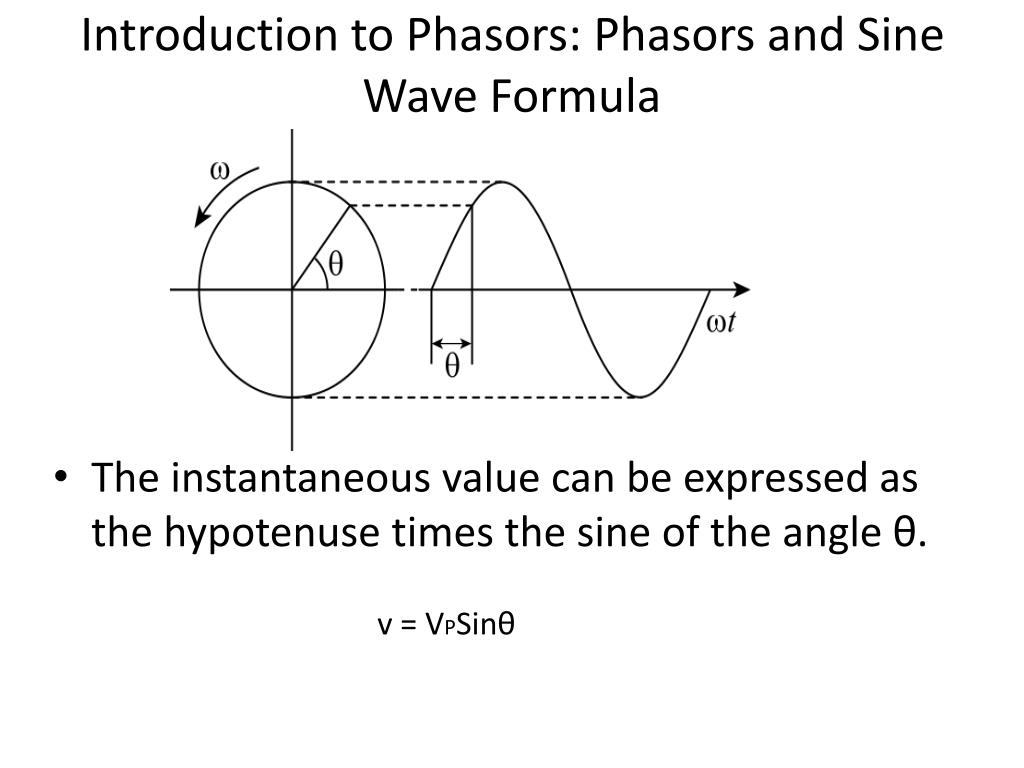
Introduction To Phasors Definition Examples Diagrams Vrogue Co Phasor notation (also known as angle notation) is a mathematical notation used in electronics engineering and electrical engineering.a vector whose polar coordinates are magnitude and angle is written . [13] can represent either the vector (, ) or the complex number =, according to euler's formula with =, both of which have magnitudes of 1. A is the amplitude,; ω is the angular frequency (in radians per second),; t is time, and; ϕ is the phase angle (in radians).; phasors definition. a phasor is a complex number used to represent the magnitude and phase of a sinusoidal function, particularly in the context of alternating current (ac) electricity, signal processing, and wave mechanics.

Introduction To Phasors Definition Examples Diagrams Vrogue Co This calculus operates very much like the calculus we developed in "complex numbers" and "the functions e x and e jθ " for manipulating complex numbers. we apply our calculus to the study of beating phenomena, multiphase power, series rlc circuits, and light scattering by a slit. this page titled 3.1: introduction to phasors is shared under a. Introduction to phasors 1: sinusoidal signals if all the sources in a circuit are sinusoidal sources and our interest is in only the steady state component (because the transient component decays to approximately zero within a short time after connecting the circuit to the ac source), we can use the phasor domain technique to analyze the circuit. A phasor is a complex valued number that represents a real valued sinusoidal waveform. specifically, a phasor has the magnitude and phase of the sinusoid it represents. figure 1.5.1 and 1.5.2 show some examples of phasors and the associated sinusoids. it is important to note that a phasor by itself is not the signal. The sum of two signals with common frequencies but different amplitudes and phases is. a1cos(ωt φ1) a2cos(ωt φ2) the rotating phasor representation for this sum is. (a1ej φ 1 a2ej φ 2)ej ω t. the new phasor is a1ej φ 1 a2ej φ 2, and the corresponding real signal is x(t) = re[(a1ej φ 1 a2ej φ 2)ej ω t].

Comments are closed.