Interface Display Matlab Simulink

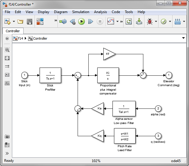
Explore Your Models Easily With The Interface View в Guy On Simulink Interface display. view and trace the input and output signals of a simulink ® model or subsystem. published: 10 sep 2014. bridging wireless communications design and testing with matlab. feedback. mathworks. accelerating the pace of engineering and science. mathworks is the leading developer of mathematical computing software for engineers. The interface view enables you to trace the hand off and receipt between such blocks by way of colored highlights. trace connections in a subsystem. this example shows how to use the display of model interfaces to examine, trace, and understand the flow of signals and buses. this model propagates buses into referenced models.

Working With Simulink Matlab Tutorials Youtube Once the model has been simulated or updated once, the interface view displays for each port its data type and sample time, making it easier to understand the model. one more thing to note. when in interface display, you cannot edit the model. this is convenient when your goal is just to explore and understand the model without modifying it. The display block shows the value of the input data. you can specify the frequency of the display. for numeric input data, you can also specify the format of display. if the block input is an array, you can resize the block vertically or horizontally to show more than just the first element. if the block input is a vector, the block. Step 3 of 3 in component based modeling guidelines. defining the interface of a model component, such as a simulink ® subsystem, subsystem reference, or model reference, is a key first step before others can use it. agreeing on an interface helps determine how to break down the functionality of a large system into components. Models — by default, the component interface view displays the input ports on the left and the output ports on the right. to move a port in the component interface view, select the port and use the arrow keys. to save the modified the component interface view port locations, save the model.

Getting Started With Simulink In Matlab Designing A Model Step 3 of 3 in component based modeling guidelines. defining the interface of a model component, such as a simulink ® subsystem, subsystem reference, or model reference, is a key first step before others can use it. agreeing on an interface helps determine how to break down the functionality of a large system into components. Models — by default, the component interface view displays the input ports on the left and the output ports on the right. to move a port in the component interface view, select the port and use the arrow keys. to save the modified the component interface view port locations, save the model. To display bus hierarchy: select a bus in your model. in the simulink toolstrip, on the signal tab, click signal hierarchy. a signal hierarchy viewer opens, showing the signal hierarchy for the selected bus. for example, this signal hierarchy viewer shows the signal hierarchy for a bus named main bus. Composite interface guidelines. combine signals, messages, or connections to simplify model appearance. step 1: explore composite interfaces. step 2: compare capabilities of composite interfaces. bus capable blocks identify the blocks that support virtual buses, nonvirtual buses, and arrays of buses.

Interface Display Matlab Simulink To display bus hierarchy: select a bus in your model. in the simulink toolstrip, on the signal tab, click signal hierarchy. a signal hierarchy viewer opens, showing the signal hierarchy for the selected bus. for example, this signal hierarchy viewer shows the signal hierarchy for a bus named main bus. Composite interface guidelines. combine signals, messages, or connections to simplify model appearance. step 1: explore composite interfaces. step 2: compare capabilities of composite interfaces. bus capable blocks identify the blocks that support virtual buses, nonvirtual buses, and arrays of buses.

Trace Connections Using Interface Display Matlab Simulink

Comments are closed.