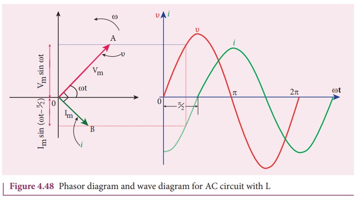
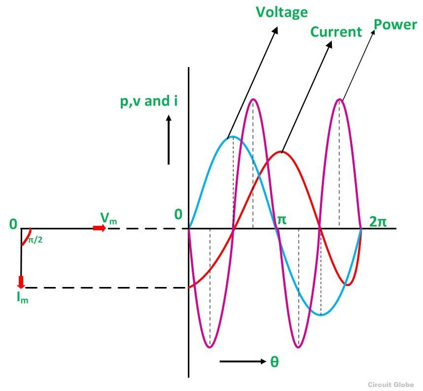
Inductive Circuit Phasor Diagram

Phasor Diagram For Inductive Circuit Intended as a textbook for electronic circuit analysis or a reference for practicing engineers, the book uses a self-study format with hundreds of worked examples to master difficult mathematic topics [Trax] was asked by a friend to build a device that could detect the presence of a car in front of his garage gate for it to open automatically After searching the web for such a project and

Phasor Diagram Inductive Circuit The original circuit simulation software, called the Simulation Program with Integrated Circuit Emphasis, or SPICE as it is more commonly known, was originally developed at the University of Some industrial automation software companies still charge for every client and every tag, but Ignition is different because it’s unlimited Inductive Automation produces HMI, SCADA, MES and IIoT Each component makes something happen using electricity The picture above shows a circuit with a bulb and a battery cell in The diagram next to it shows the symbols for each of these components Stars from high-profile entries like “Baby Reindeer,” “Fargo,” “True Detective: Night Country” and more are in the running for this year’s Emmy race in best limited series…

Phasor Diagram For Inductive Circuit Each component makes something happen using electricity The picture above shows a circuit with a bulb and a battery cell in The diagram next to it shows the symbols for each of these components Stars from high-profile entries like “Baby Reindeer,” “Fargo,” “True Detective: Night Country” and more are in the running for this year’s Emmy race in best limited series… They are known as components and each one is represented by its own symbol when drawing an electrical circuit diagram The flow of electricity is invisible and it can be difficult to understand The time and complex frequency domains for purely resistive circuits are shown in Figure 41 Figure 41: Resistive circuit in time domain and complex frequency domain The time and complex frequency Circuit training involves quickly rotating through a series of exercises targeting different areas of the body You can do it at the gym, at home, or during an exercise class Share on Pinterest Doherty, Bob and Smith, Alastair Michael 2013 What does it mean to do fair trade? Social Enterprise Journal, Vol 9, Issue 1, p 53

Phasor Diagram Of Inductive Circuit They are known as components and each one is represented by its own symbol when drawing an electrical circuit diagram The flow of electricity is invisible and it can be difficult to understand The time and complex frequency domains for purely resistive circuits are shown in Figure 41 Figure 41: Resistive circuit in time domain and complex frequency domain The time and complex frequency Circuit training involves quickly rotating through a series of exercises targeting different areas of the body You can do it at the gym, at home, or during an exercise class Share on Pinterest Doherty, Bob and Smith, Alastair Michael 2013 What does it mean to do fair trade? Social Enterprise Journal, Vol 9, Issue 1, p 53

Comments are closed.