Hunter Ceiling Fan With Light Wiring Diagram

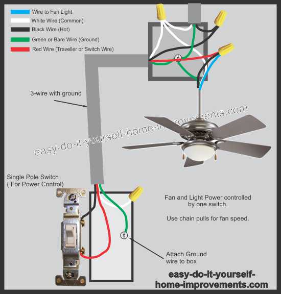
Hunter Ceiling Fan Wiring Schematic To wall switch wire for separate control of light fixture, or connect blk wht wire from fan to ceiling black wire if there is no separate wall switch wire for the light fixture. 1 2 figure 4c wiring diagram 4. connect the wires as shown in figure 4c. to connect the wires, twist the bare metal leads to gether. place a wire nut over the. Installation & wiring. helpful information about wiring, mounting options, downrods and more.

Hunter Fan Wiring Schematic Step 2: identify the wires. with the power off, remove the fan’s canopy to access the wiring. identify the wires coming from the ceiling and those connected to the fan motor, light kit, and wall switch. refer to the wiring diagram provided by hunter for guidance. Ight level decrease–off)turning the light off resets the dimming. xt press of the light button will start at maximum brightness.fan operation:press the high. medium, or low sp. d buttons to turn the ceiling fan on at the desire. speed. refer to figure 4.press the fan off key to turn the ceiling fan off.fo. Figure 5 wiring diagram earth power˜ wires˜ in ˜ ceiling blue blue brown black white 1 2 connections:˜ ˜ brown (optional line)˜ wall switch wire for ˜ separate control of light kit green yellow˜ wire from hanger 3 wires ˜ from fan (note: wall switch ˜ must be acceptable ˜ as a general use˜ switch.) connect blk wht wire from fan˜. Step 1: pre installation. 1. select the installation site: normally this is near the center of the room, often replacing a light fixture. make certain that ample clearance is left for the rotating fan blades. for maximum efficiency, no obstructions (walls, posts, etc.) should be within 24" of the tips of the blades.

Hunter Ceiling Fan Wiring Schematic Figure 5 wiring diagram earth power˜ wires˜ in ˜ ceiling blue blue brown black white 1 2 connections:˜ ˜ brown (optional line)˜ wall switch wire for ˜ separate control of light kit green yellow˜ wire from hanger 3 wires ˜ from fan (note: wall switch ˜ must be acceptable ˜ as a general use˜ switch.) connect blk wht wire from fan˜. Step 1: pre installation. 1. select the installation site: normally this is near the center of the room, often replacing a light fixture. make certain that ample clearance is left for the rotating fan blades. for maximum efficiency, no obstructions (walls, posts, etc.) should be within 24" of the tips of the blades. Connect the black (ungrounded) wire from the ceiling to the black wire from the fan. 03. connect the second ungrounded (light) wire from the ceiling to the blue wire from the fan. 04. connect the three grounding wires (green, green yellow stripe, or bare copper) coming from the ceiling, downrod, and hanging bracket. Reattach the patented breakaway connector to the end of the pull chain. 5. insert the reversing switch into the square hole on the side of the modular accessory light kit. install and tighten the two screws you removed in step 1, substep 1. 6. carefully place the capacitors in the modular ac cessory light kit.

Comments are closed.