How To Use A Fuse Circuit Tester Wiring Diagram

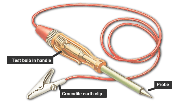
How To Use A Fuse Circuit Tester Wiring Diagram A test light is a simple device that can tell you if power or ground is present at a particular circuit or fuse. the test light consists of a sharp probe, indicator light bulb and a wire lead with a clip. this tool is easy to use and is reasonably priced on amazon (about $20.00 us) and. ** timeline below if you would like to jump to a specific section ** a test light is a simple, quick tool to test for electrical issues in your car. they may.

How To Use A Fuse Circuit Tester Wiring Diagram Shop for new auto parts at 1aauto 1aau.to c 336 l toolsin the video, 1a auto shows how to check your fuses with a test light.🔧 list of tools used. Connect the clamp side of the test light to the battery positive (positive power source). connect the other end to the wire (or circuit) in question. when the test light illuminates, it means there is a short to ground. be sure it is the correct circuit you are testing. the circuit may be grounded for a reason. 2. turn the meter on and set it to measure continuity. turn the dial on the multimeter so it points to the continuity setting, which looks like 5 curved vertical lines. before you test the fuse, put the positive and negative leads together and listen for the meter to beep to ensure it’s working properly. The light should light when connected as shown with the a c clutch fuse removed. first, find the hot terminal by connecting the test light clip to ground. then move the test light clip to b 12v and test the opposite side of the fuse. it should show a ground coming back through the load.

Wiring Diagrams Automotive Fuses 2. turn the meter on and set it to measure continuity. turn the dial on the multimeter so it points to the continuity setting, which looks like 5 curved vertical lines. before you test the fuse, put the positive and negative leads together and listen for the meter to beep to ensure it’s working properly. The light should light when connected as shown with the a c clutch fuse removed. first, find the hot terminal by connecting the test light clip to ground. then move the test light clip to b 12v and test the opposite side of the fuse. it should show a ground coming back through the load. Make sure your continuity tester is working by touching the metal probe to its corresponding clip. if it is working, it should light up. similarly to a multimeter, simply touch the probe and clips to the end of a fuse to test it. if the tester lights up, the fuse is working. be sure there is no current running through the fuse before testing. Additionally, the wiring diagram may include color codes for the wires, making it easier to identify and trace them. overall, a fuse block wiring diagram is a valuable resource for anyone working on the electrical system of a vehicle. it provides a visual representation of the electrical connections and helps ensure correct and safe wiring.

Comments are closed.