How To Make A Pure Sin Wave Inverter Using Arduino

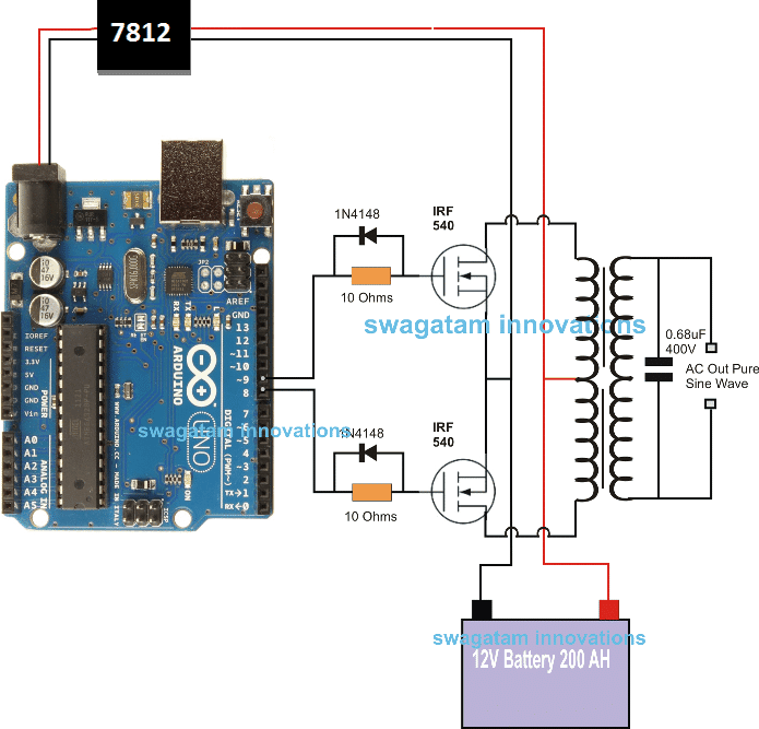
Arduino Pure Sine Wave Inverter Circuit With Full Program Code How to setup. to set up the automatic voltage correction circuit, feed a stable 230v or 110v as per your inverter specs to the input side of the circuit. next, adjust the 10k preset carefully such that the red leds just light up. that's all, seal the preset and connect the circuit with the above arduino board for implementing the intended. Followings are the main components used in single phase pure sine wave inverter using arduino. i provided a brief explanation of each component below: arduino: arduino uno r3 is used to generate control signals for mosfet driver using spwm ( sinusoidal pulse width modulation technique). for more information on this technique, you can check my.

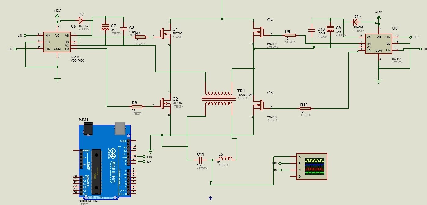
Single Phase Pure Sine Wave Inverter Using Arduino Author. pure sine wave inverter using arduino. inverter circuits are often needed where it is not possible to get ac supply from the grid. an inverter circuit is used to convert dc power to ac power and it can be divided into two types that is pure sine wave inverters or modified square wave inverters. these pure sine wave inverters are very. In this video i will show how to make a basic 50 hz pure sin wave inverter using arduino. i have discussed the arduino code but, if you don;t want the to lis. 𝗣𝘂𝗿𝗲 𝘀𝗶𝗻𝗲 𝘄𝗮𝘃𝗲 𝗶𝘀 𝗮𝗹𝘄𝗮𝘆𝘀 𝗻𝗲𝗲𝗱𝗲𝗱,𝗣𝘂𝗿𝗲 𝗦𝗶𝗻𝗲 𝗪𝗮𝘃𝗲 ⚡ inverters are. How it works. as shown in the above figure, the working of this arduino based full bridge sinewave inverter can be understood with the help of the following points: the arduino is programmed to genearte appropriately formatted spwm outputs from pin#8 and pin#9. while one of the pins is generating the spwms, the complementary pin is held low.

Comments are closed.