How To Draw Phasor Diagram For Pure Inductive Circuit Vrogue Co

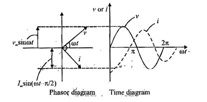
How To Draw Phasor Diagram For Pure Inductive Circuit Vrogue Co The circuit which contains only inductance (l) and not any other quantities like resistance and capacitance in the circuit is called a pure inductive circuit. in this type of circuit, the current lags behind the voltage by an angle of 90 degrees. contents: explanation and derivation of inductive circuit. The formula for calculating xl is: . x l = 2 · π · f · l. . current (i) lags applied voltage (e) in a purely inductive circuit by 90° phase angle. . the phasor diagram shows the applied voltage (e) vector leading (above) the current (i) vector by the amount of the phase angle differential due to the relationship between voltage and current.

How To Draw Phasor Diagram For Pure Inductive Circuit Vrogue Co Phasor diagram of purely inductive circuit. the phasor diagram of a purely inductive circuit is shown in figure (2). from figure (2) it is clear that the current in the circuit lag behind the voltage by 90º. impedance of purely inductive circuit. impedance ‘z’ of any circuit is given by, \[z=\sqrt{{{r}^{2}} {{x}^{2}}}\] where, r. The phase of an alternating quantity at any instant in time can be represented by phasor diagrams. thus phasor diagrams can be thought of as representing “functions of time”. a complete sine wave can be constructed by a single vector rotating anti clockwise at an angular velocity of ω = 2πƒ, where ƒ denotes the frequency of the waveform. Example 3: given a voltage source with v(t) = 20 sin(50t π 4) volts and a current i(t) = 10 sin(50t– π 4) amperes. the phasor representation of the voltage is 20∠45∘ and the current is 10∠ − 45∘. the phase difference between the voltage and the current is 90∘, which means the voltage leads the current by 90∘. Cosϕ = r z, as diagramed in. phasor diagram for an rlc series circuit: phasor diagram for an rlc series circuit. \phi is the phase angle, equal to the phase difference between the voltage and current. for example, at the resonant frequency (ν0 = 1 2π√lc) or in a purely resistive circuit, z=r, so that cosϕ=1.

How To Draw Phasor Diagram For Pure Inductive Circuit Vrogue Co Example 3: given a voltage source with v(t) = 20 sin(50t π 4) volts and a current i(t) = 10 sin(50t– π 4) amperes. the phasor representation of the voltage is 20∠45∘ and the current is 10∠ − 45∘. the phase difference between the voltage and the current is 90∘, which means the voltage leads the current by 90∘. Cosϕ = r z, as diagramed in. phasor diagram for an rlc series circuit: phasor diagram for an rlc series circuit. \phi is the phase angle, equal to the phase difference between the voltage and current. for example, at the resonant frequency (ν0 = 1 2π√lc) or in a purely resistive circuit, z=r, so that cosϕ=1. Phasor diagrams are graphical representations used to analyze and visualize the characteristics of alternating current (ac) circuits. they provide a way to simplify complex ac circuit calculations and understand the relationships between voltage, current, and impedance. a phasor diagram consists of vectors that represent the amplitude and phase. The process of drawing a phasor diagram involves identifying ac circuit elements, plotting the reference and other vectors, adding complex numbers, and interpreting the vectors. increased accuracy in phasor diagrams can be achieved by ensuring calculations are correct, vectors are marked clearly, the right reference vector is chosen, the tools.

Comments are closed.