Gpio Pins On Raspberry Pi Technology Tutorials

Gpio Pins On Raspberry Pi Technology Tutorials Before starting with the gpio pins practice, we need to do a few steps on the raspberry pi to make sure that everything is ready: start by updating your system. sudo apt update. sudo apt upgrade. install the rpi.gpio package (it should be pre installed on most versions) sudo apt install python3 rpi.gpio. It allows you to establish communication with other microcontroller devices, sensors, or displays, for example. you can connect multiple i2c devices to the same pins as long they have a unique i2c address. the raspberry pi i2c pins are gpio 2 and gpio 3: sda: gpio 2. scl: gpio 3.

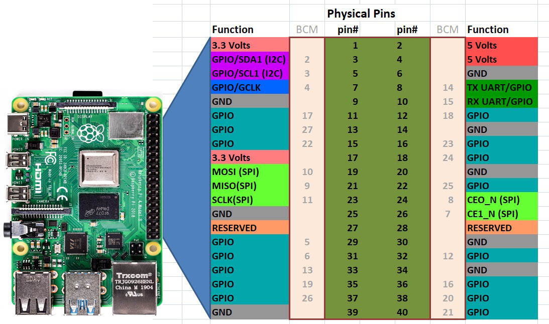
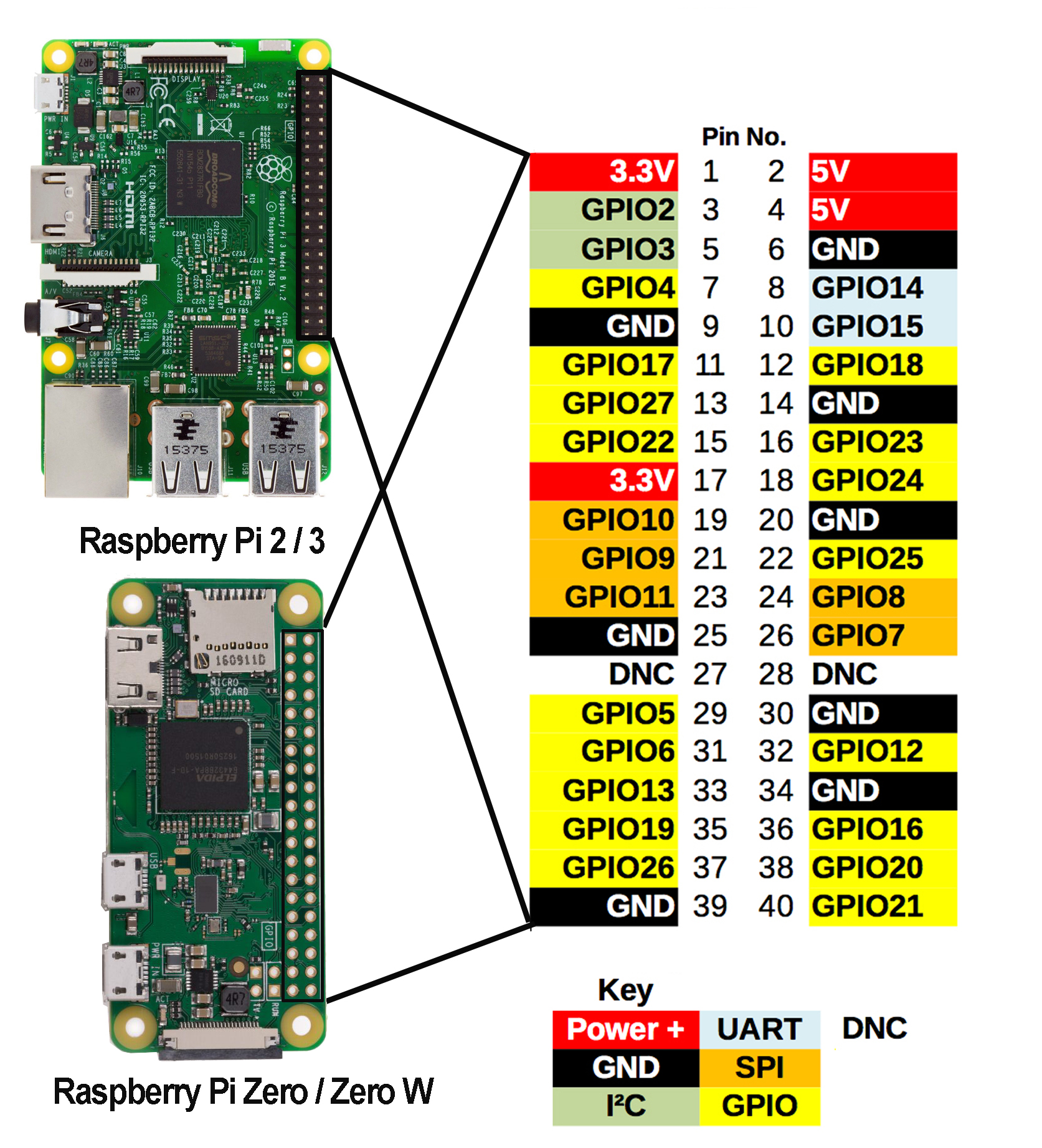
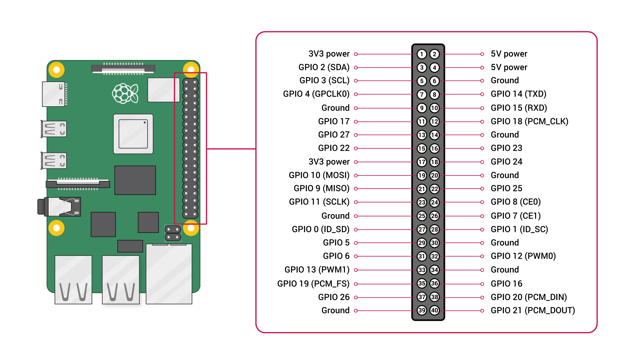
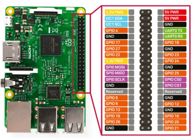
Gpio Pin Diagram Raspberry Pi Raspberry pi gpio diagrams. now, let’s get started on this raspberry pi gpio tutorial. we will be taking a look at the different types of pins available, how to enable the modules, what a breakout kit is, and finally, how to build and program a simple circuit. if you own a raspberry pi b , 2, zero, 3, 4, or 5, you will have 40 pins in total. Simplified diagram. when you take the raspberry pi board in front of you with the usb ports at the bottom, the gpio pin 1 is in the top left corner. number 2 is in the top right corner (not below), and from there it goes from left to right, and the next line, as if reading a book. also: i've tested hundreds of linux apps, here are the ones i. The output functions for this pin are now available. with the following two commands we can firstly switch the led on and then switch it off again: gpio.output(23, gpio.high) gpio.output(23, gpio.low) this command simply says whether a voltage of 3.3v (high) or 0v (low) should be applied. The raspberry pi offers up its gpio over a standard male header on the board. over the years the header has expanded from 26 pins to 40 pins while maintaining the original pinout. if you're coming to the raspberry pi as an arduino user, you're probably used to referencing pins with a single, unique number.

Introduction To The Raspberry Pi Gpio And Physical Computing Sparkfun The output functions for this pin are now available. with the following two commands we can firstly switch the led on and then switch it off again: gpio.output(23, gpio.high) gpio.output(23, gpio.low) this command simply says whether a voltage of 3.3v (high) or 0v (low) should be applied. The raspberry pi offers up its gpio over a standard male header on the board. over the years the header has expanded from 26 pins to 40 pins while maintaining the original pinout. if you're coming to the raspberry pi as an arduino user, you're probably used to referencing pins with a single, unique number. Here's a basic overview: connect the positive leg (longer one) of an led to a resistor (around 330Ω), then connect the other end of the resistor to one of the gpio pins on the raspberry pi. connect the negative leg (shorter one) of the led to one of the ground (gnd) pins on the pi. Here's a quick overview of these communication protocols! spi pins – the serial peripheral interface (spi) is a communication protocol used to transfer data between micro computers like the raspberry pi and peripheral devices. the miso pin receives data, and the mosi pin sends data from the raspberry pi.

Raspberry Pi Gpio A Beginner S Guide To Getting Started Here's a basic overview: connect the positive leg (longer one) of an led to a resistor (around 330Ω), then connect the other end of the resistor to one of the gpio pins on the raspberry pi. connect the negative leg (shorter one) of the led to one of the ground (gnd) pins on the pi. Here's a quick overview of these communication protocols! spi pins – the serial peripheral interface (spi) is a communication protocol used to transfer data between micro computers like the raspberry pi and peripheral devices. the miso pin receives data, and the mosi pin sends data from the raspberry pi.

Comments are closed.