Gm External Voltage Regulator Wiring

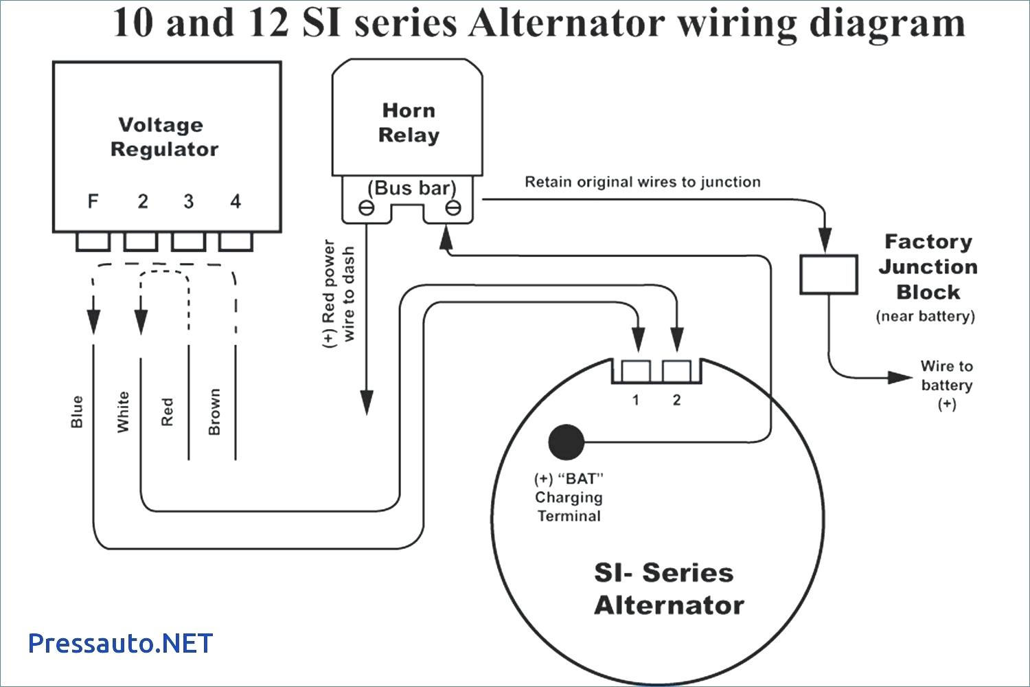
Gm Alternator Wiring Diagram External Regulator Gm externally regulated alternator to voltage regulator wiring . wiring instructions for the early gm delco remy external regulated alternator. how to wire an external voltage regulator on a gm vehicle. the early gm alternator is the 10dn series alternator and was used on gm vehicles from about 1963 1970. The number 1 wire on the 10 or 12 si is connected to the charge warning light on the dash. the number 2 wire is what is called the voltage sensing wire. when converting from an external voltage regulator to an internal such as the 12 si, many enthusiasts merely connect the number 2 voltage sensing wire directly to the output terminal.

Gm External Voltage Regulator Wiring Gm external regulator alternator wiring refers to the electrical connections required to connect an external voltage regulator to a gm alternator. this type of wiring setup is commonly found in older gm vehicles, particularly those manufactured in the 1970s and 1980s. the external regulator is responsible for regulating the electrical output of. A typical 3 wire alternator wiring diagram with an internal voltage regulator. computer controlled voltage regulation. many late model vehicles use the engine computer, which is often referred to as the powertrain control module (pcm), to control alternator output. most modules use an internal driver to turn the alternator’s field circuit on. The wiring diagram provides a visual representation of the connections and electrical components involved in the voltage regulator circuit. the gm voltage regulator wiring diagram typically includes information about the battery connection, the ignition switch connection, the voltage regulator terminal connections, and the alternator connection. The wiring diagram for an alternator external voltage regulator typically shows the connections between the voltage regulator, alternator, battery, and ignition switch. it may also include additional components such as fuses, relays, and diodes. the diagram provides a visual representation of how the various components are connected, allowing.

Alternator With External Voltage Regulator The wiring diagram provides a visual representation of the connections and electrical components involved in the voltage regulator circuit. the gm voltage regulator wiring diagram typically includes information about the battery connection, the ignition switch connection, the voltage regulator terminal connections, and the alternator connection. The wiring diagram for an alternator external voltage regulator typically shows the connections between the voltage regulator, alternator, battery, and ignition switch. it may also include additional components such as fuses, relays, and diodes. the diagram provides a visual representation of how the various components are connected, allowing. So if your alternator housing is unmarked, look from the rear of the alternator: the #1 terminal is on the left and the #2 on the right. you only need an ignition wire to the #1 terminal to make an si series alternator work. the #2 terminal is for voltage sensing, and is optional. the #2 voltage sensing terminal allows the voltage regulator to. The one wire design eliminates the need for an external voltage regulator, making the installation process easier. to wire a one wire gm alternator, you will need a few essential components. first, you will need the alternator itself, which can usually be found at an auto parts store or salvage yard.

Comments are closed.