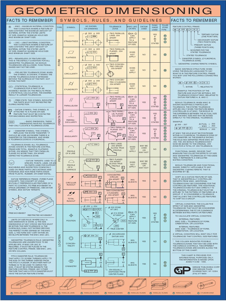
Geometric Tolerance Chart

Geometric Tolerance Chart Engineering Tolerance Geometry Learn about the symbols and concepts of geometric dimensioning and tolerancing (gd&t) with this comprehensive guide. download the free wall chart for a quick reference and click on the links to learn more about each gd&t symbol or topic. Learn about the history, purpose, and content of the asme y14.5 standard, a comprehensive gd&t system for engineering drawings. find symbols, rules, definitions, and examples for form, orientation, location, profile, and runout tolerancing.

Gd T 101 An Introduction To Geometric Dimensioning And Tolerancing Geometric dimensioning and tolerancing. geometric dimensioning and tolerancing (gd&t) is a system for defining and communicating engineering tolerances via a symbolic language on engineering drawings and computer generated 3d models that describes a physical object's nominal geometry and the permissible variation thereof. Gd&t symbols reference guide from sigmetrix. in geometric dimensioning and tolerancing (gd&t), a unique set of gd&t symbols are used to define the relationships between part features and measurement references. designers and engineers utilize this international language on their drawings to accurately describe part features on the basis of size. Gd&t wall chart true position calculator blog gd&t quiz print reading quiz guide to team gd&t training orthographic projection chart drill tap chart asme y14.5 2009 vs. 2018 standard asme vs iso gd&t standards comparison ask a gd&t question industry readlines newsletter. Learn how to use 16 symbols for geometric tolerancing on drawings, categorized by tolerance type and geometrical characteristic. see examples of true position theory and tolerance zone specification.

Geometric Tolerancing Reference Chart Gd&t wall chart true position calculator blog gd&t quiz print reading quiz guide to team gd&t training orthographic projection chart drill tap chart asme y14.5 2009 vs. 2018 standard asme vs iso gd&t standards comparison ask a gd&t question industry readlines newsletter. Learn how to use 16 symbols for geometric tolerancing on drawings, categorized by tolerance type and geometrical characteristic. see examples of true position theory and tolerance zone specification. This section explains the four types of geometric tolerances: form tolerance, orientation tolerance, location tolerance, and run out tolerance. it also provides an overview of the maximum material requirement, which is essential to designing the mating of shafts and bores, and the least material requirement, which is effective in designing the thickness of pipes and other parts where. Cylindrical fits and tolerances table for ip and metric. the ansi b4.1 standard arranged fits classes in three general groups according to the field and type of usage. preferred tolerance limits fits ansi b4.1. this standard defines preferred limits and fits for press fits applications of non threaded cylindrical features.

Comments are closed.