Engineering Drawings Gd T For The Quality Engineer

Engineering Drawings Gd T For The Quality Engineer Gd&t and the quality engineer. as a quality engineer you will be expected to be able to read and interpret engineering drawings and the gd&t associated with that drawing. this will allow you to understand the intent of the product designer, which will allow you to assess the conformance of a unit coming off of your production line. Asme y14.5 is an established, widely used gd&t standard containing all the necessary information for a comprehensive gd&t system. the asme y14.5 standard establishes symbols, definitions, and rules for geometric dimensioning and tolerancing. the purpose of the standard is to ensure clear communication of detailed information throughout the.

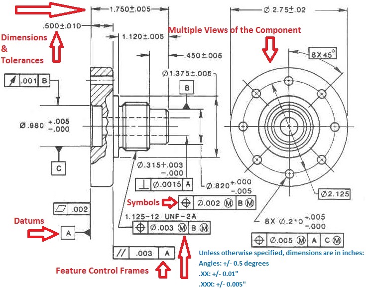
Engineering Drawings Gd T For The Quality Engineer The use of gd&t can help to reduce misinterpretation, reduce scrap and rework, and increase the efficiency of the manufacturing and inspection processes. by using gd&t, engineers and manufacturers can communicate their design intent more clearly and accurately, leading to improved quality, cost savings, and increased productivity. Geometric dimensioning and tolerancing (gd&t) is a language of symbols used to describe a part’s nominal geometry and the allowable tolerance for variation. when applied properly the design engineer can concisely define a features location, size, shape and orientation on the part. gd&t is intended as an addition to the coordinate dimensioning. Currently, the gd&t standard is defined by the american society of mechanical engineers (asme y14.5 2018) for the usa and iso 1101 2017 for the rest of the world. it concerns mostly the overall geometry of the product, while other standards describe specific features such as surface roughness, texture, and screw threads. In gd&t, each feature of a manufactured part is specified by datums and controls. our gd&t guided study courses enhance your skills related to choosing datums and feature controls, per asme y14.5, through drawing assignments, quizzes, and email q&a with an expert instructor. courses can be completed at your own pace within a 6 week session.

Engineering Drawings Gd T For The Quality Engineer Geometric Currently, the gd&t standard is defined by the american society of mechanical engineers (asme y14.5 2018) for the usa and iso 1101 2017 for the rest of the world. it concerns mostly the overall geometry of the product, while other standards describe specific features such as surface roughness, texture, and screw threads. In gd&t, each feature of a manufactured part is specified by datums and controls. our gd&t guided study courses enhance your skills related to choosing datums and feature controls, per asme y14.5, through drawing assignments, quizzes, and email q&a with an expert instructor. courses can be completed at your own pace within a 6 week session. Advance your technical career with our self paced gd&t online training for individuals. designed to make you the go to engineer, our courses equip you with the confidence to use gd&t correctly in any role. you’ll learn practical skills you’ll use every day on the job. 24 7 video on demand access. learn at your own pace. Geometric dimensioning and tolerancing ( gd&t) is a system for defining and communicating engineering tolerances via a symbolic language on engineering drawings and computer generated 3d models that describes a physical object's nominal geometry and the permissible variation thereof. gd&t is used to define the nominal (theoretically perfect.

Comments are closed.