Engineering Drawing Reference Find Number

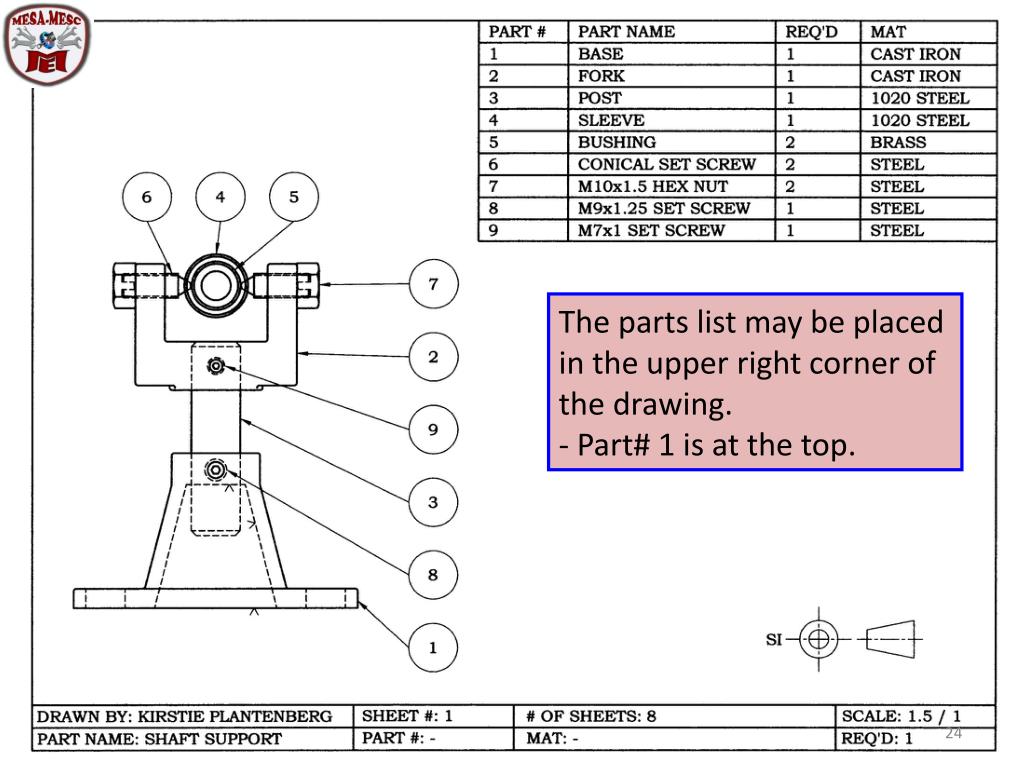
4 Ways To Read Engineering Drawings Wikihow Using only the find number in the drawing callout saved time by avoiding the requirement to initially draw and or update a part number in multiple places. yes, we used to worry about such things. while times have certainly changed it's still rather common for engineering drawings to emulate this exact format, but with better automation. Our drawing policy includes the drawing requirements manual (drm) issued by global engineering documents which specifies in sections 7.10 and 7.11, and have been referenced and interpretted by each group here as to why they would use "x reqd" next to a find number balloon. it's not required, but if used it should be as "x reqd".

How To Read Engineering Drawings вђ Learnweldingsymbols Sorry if i wasn't clear, kenat, i'm talking about find numbers in notes that have already been called out on the field of drawing via balloon. such as: notes: 1. bond (fn1) to (fn6) with fn 10. where find number 1 and find number 6 have already been designated in a view with a balloon. 1. optional. they just save drawing space. 2. used for cross referencing only. so, by their nature they already are "reference", so there is no need to create "reference reference" balloon, unless item quantities may become confusing, as 3ddave already mentioned. "for every expert there is an equal and opposite expert". A general note applies generally and is not called out with flags. 2. find number: "fn" meaning "find number" refers to the ordinal number that gives an id tag to one of the constituents in a parts list (list of materials, bill of materials). thus "fasten using fn7" refers to a fastener that is "find number" 7 in the list. fos: feature of size. The gsfc engineering drawing standards manual is the official source for the requirements and interpretations to be used in the development and presentation of engineering drawings and related documentation for the gsfc. the mechanical engineering branch, mechanical systems division, has been delegated.

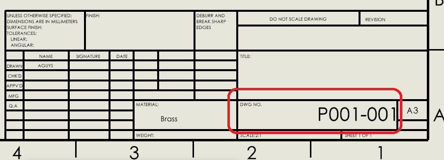
Ppt Engineering Drawing Powerpoint Presentation Free Download Id A general note applies generally and is not called out with flags. 2. find number: "fn" meaning "find number" refers to the ordinal number that gives an id tag to one of the constituents in a parts list (list of materials, bill of materials). thus "fasten using fn7" refers to a fastener that is "find number" 7 in the list. fos: feature of size. The gsfc engineering drawing standards manual is the official source for the requirements and interpretations to be used in the development and presentation of engineering drawings and related documentation for the gsfc. the mechanical engineering branch, mechanical systems division, has been delegated. To read and interpret engineering drawings effectively, start by examining the title block for important contextual information. familiarize yourself with the purpose, part number, material, finish, and other details provided. next, visualize the assembly in 3d, using isometric views provided in the drawing as a guide. An engineering drawing provides details such as first angle projections, hidden lines, extension lines, etc., which are crucial for precise manufacturing. they include cross sectional views or an auxiliary view that reveal hidden features and internal details, which a 3d model alone cannot fully convey. while 3d models are valuable for visual.

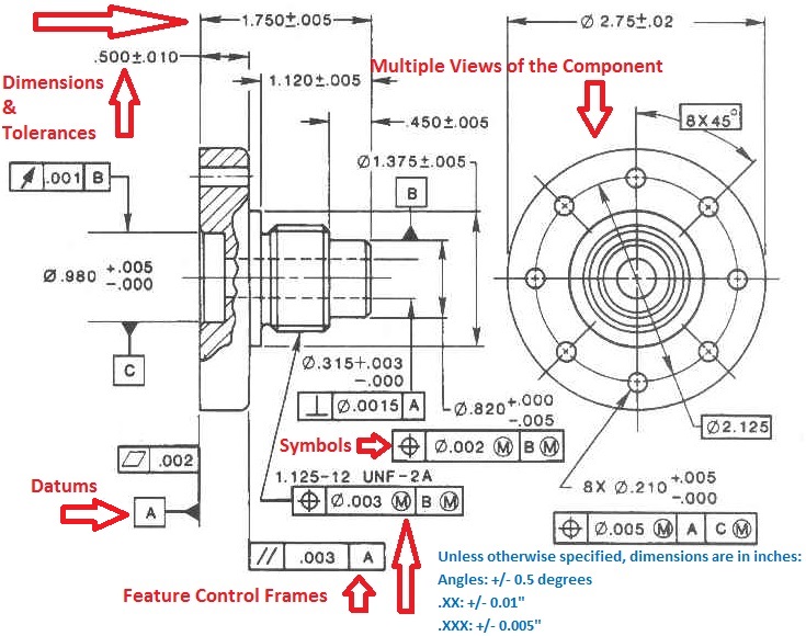
Engineering Drawings Gd T For The Quality Engineer To read and interpret engineering drawings effectively, start by examining the title block for important contextual information. familiarize yourself with the purpose, part number, material, finish, and other details provided. next, visualize the assembly in 3d, using isometric views provided in the drawing as a guide. An engineering drawing provides details such as first angle projections, hidden lines, extension lines, etc., which are crucial for precise manufacturing. they include cross sectional views or an auxiliary view that reveal hidden features and internal details, which a 3d model alone cannot fully convey. while 3d models are valuable for visual.

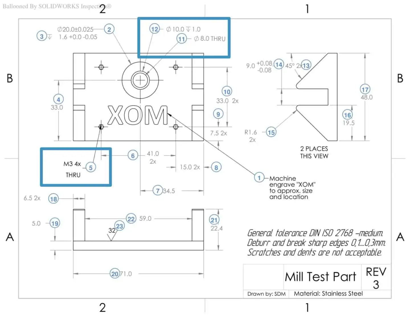
How To Prepare A Perfect Technical Drawing Xometry Europe

Comments are closed.