Engineering Drawing Points

Projections Of Points Engineering Drawing Youtube Engineering drawing basics explained. an engineering drawing is a subcategory of technical drawings. the purpose is to convey all the information necessary for manufacturing a product or a part. engineering drawings use standardised language and symbols. this makes understanding the drawings simple with little to no personal interpretation. The purpose of this guide is to give you the basics of engineering sketching and drawing. we will treat “sketching” and “drawing” as one. “sketching” generally means freehand drawing. “drawing” usually means using drawing instruments, from compasses to computers to bring precision to the drawings. this is just an introduction.

Introduction Of Engineering Drawing And Projection Of Point Youtube A.introduction to engineering drawing and its importance in mechanical design and manufacturing. engineering drawing, often referred to as technical or mechanical drawing, is the universal language of engineers and technicians. it’s an essential skill that translates complex ideas and theoretical designs into visual blueprints. Unlock the secrets of precise point projection in engineering drawing with our comprehensive tutorial! 📐🔍 follow along as we navigate through different qua. The three view multiview drawing is the standard used in engineering and technology, because often the other three common views are mirror images and do not add to the knowledge about the object. the standard views used in a three view drawing are the top, front, and right side views, arranged as shown in the figure: the width dimension is. A geometrically represented image (visual image or figure) of an object obtained on a surface or plane is referred to as a projection in an engineering drawing. a point, line, plane, solid, machine component, or building may be the object. projections in technical drawings are created based on the observer or reader of the technical drawing.

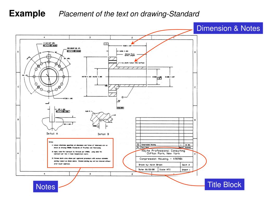
Ppt Engineering Drawing Lecture 2 Overview Of An Engineering Drawing The three view multiview drawing is the standard used in engineering and technology, because often the other three common views are mirror images and do not add to the knowledge about the object. the standard views used in a three view drawing are the top, front, and right side views, arranged as shown in the figure: the width dimension is. A geometrically represented image (visual image or figure) of an object obtained on a surface or plane is referred to as a projection in an engineering drawing. a point, line, plane, solid, machine component, or building may be the object. projections in technical drawings are created based on the observer or reader of the technical drawing. 10. autocad commands in engineering drawing. in addition to developing technical drawing skills, students will learn to use computer aided design (cad) software commands to produce 2d and 3d models and drawings. they will also learn how to read and interpret engineering drawings, including the symbols and conventions used in the industry. A point can lie with reference to both the reference planes, i.e., hp and vp. its projections are obtained by extending projectors perpendicular to the planes. in order to obtain the projection of a point lying in three dimensional space on a two dimensional plane (drawing sheet), the principal plane hp is rotated clockwise through 90° and.

What Do You Know About The Engineering Drawing в Ali S Engineering Design 10. autocad commands in engineering drawing. in addition to developing technical drawing skills, students will learn to use computer aided design (cad) software commands to produce 2d and 3d models and drawings. they will also learn how to read and interpret engineering drawings, including the symbols and conventions used in the industry. A point can lie with reference to both the reference planes, i.e., hp and vp. its projections are obtained by extending projectors perpendicular to the planes. in order to obtain the projection of a point lying in three dimensional space on a two dimensional plane (drawing sheet), the principal plane hp is rotated clockwise through 90° and.
Engineering Drawing Points

Comments are closed.