Edit And Draw Objects In The 3d View Relux

Edit And Draw Objects In The 3d View Relux Informatik Ag Base object > prism. start with the design of a staircase using the command " place new prism". draw object in the 3d view. each mouse click on your working plane creates a new point. after you have defined the last point, terminate with " return" or double click the last point. to exit the edit mode, press " esc" . Draw object in the 3d view. each mouse click on your working plane creates a new point. after you have defined the last point, terminate with “return” or double click the last point. to exit the edit mode, press “esc“. note: during the “draw cube with the mouse“ command, you can undo wrong entries with “backspace”.

Edit And Draw Objects In The 3d View Relux Informatik Ag In this reluxdesktop tutorial for beginners, i teach you how to insert doors, windows, 3d objects and materials. 👍 subscribe for more relux tutorials like t. Base object > prism. start with the design of a staircase using the command place new prism. draw object in the 3d view. each mouse click on your working plane creates a new point. after you have defined the last point, terminate with return or double click the last point. to exit the edit mode, press esc. Tutorials. here we offer a collection of engaging tutorials that will allow you to see relux in action. these interactive materials illustrate in a practical way how certain functions and applications can be used within the relux software. you can also view our video series on . reluxdesktop display options for cad plans and. Note: during the drawing command, you can change the snap grids or use zoom functionalities. the backspace key will remove the last corner point. uncalculated 3d view of this scene. 3d objects in reluxdesktop. note: there are various kinds of 3d objects available to design the exterior scene more detailed. therefore you can select: "insert.

Relux 2017 Beta Overview Of The Beta Version New Interface And Tutorials. here we offer a collection of engaging tutorials that will allow you to see relux in action. these interactive materials illustrate in a practical way how certain functions and applications can be used within the relux software. you can also view our video series on . reluxdesktop display options for cad plans and. Note: during the drawing command, you can change the snap grids or use zoom functionalities. the backspace key will remove the last corner point. uncalculated 3d view of this scene. 3d objects in reluxdesktop. note: there are various kinds of 3d objects available to design the exterior scene more detailed. therefore you can select: "insert. Click the option "interior with plan" and follow these steps: step 1: enter project data. step 2 (for interior projects only): specify the type of interior project ( "interior scenes" > "floor" ) step 3: select a file (*.dwg or *.dxf) step 4: set the scale (often 1000 m for interior and 1 m for exterior installations) step 5: rotate the drawing. Kurt bieri. the draw objects command prompts you to select the scene. this can still be modified in the dialog if necessary. if required, you can enter an appropriate designation under “name”. under “object type”, select the desired type: add elements menu. the input options will adapt as a function of the type in question (window.

Draw Polygonal Scenes Exterior Relux Click the option "interior with plan" and follow these steps: step 1: enter project data. step 2 (for interior projects only): specify the type of interior project ( "interior scenes" > "floor" ) step 3: select a file (*.dwg or *.dxf) step 4: set the scale (often 1000 m for interior and 1 m for exterior installations) step 5: rotate the drawing. Kurt bieri. the draw objects command prompts you to select the scene. this can still be modified in the dialog if necessary. if required, you can enter an appropriate designation under “name”. under “object type”, select the desired type: add elements menu. the input options will adapt as a function of the type in question (window.

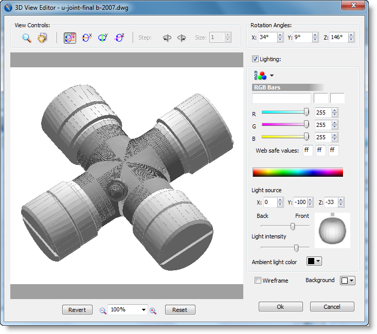
View The 3d Object In The 3d View Editor

Comments are closed.