Diy Inverter Tutorial Arduino Or 555

Homemade Inverter Diy Arduino 555 Timer Circuit Best & fast prototype ($2 for 10 pcbs): jlcpcb thanks to jlcpcb for supporting this video.in this video i show you how a very basic inverter w. 5 application. in this tutorial, we are going to make an “inverter circuit using ic 555 “. an inverter is nothing but a dc to ac converter ( a power electronic device or circuitry that changes direct current (dc) to alternating current (ac). the resulting ac frequency obtained depends on the particular device employed).

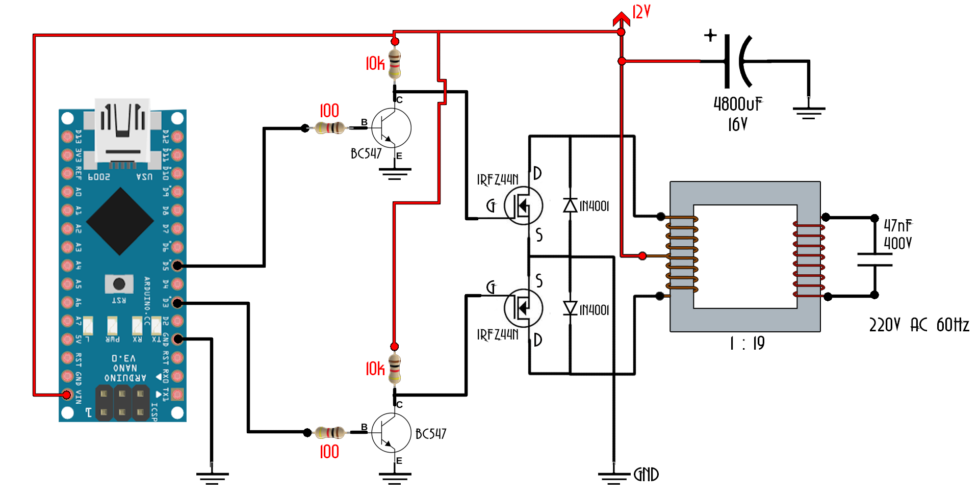
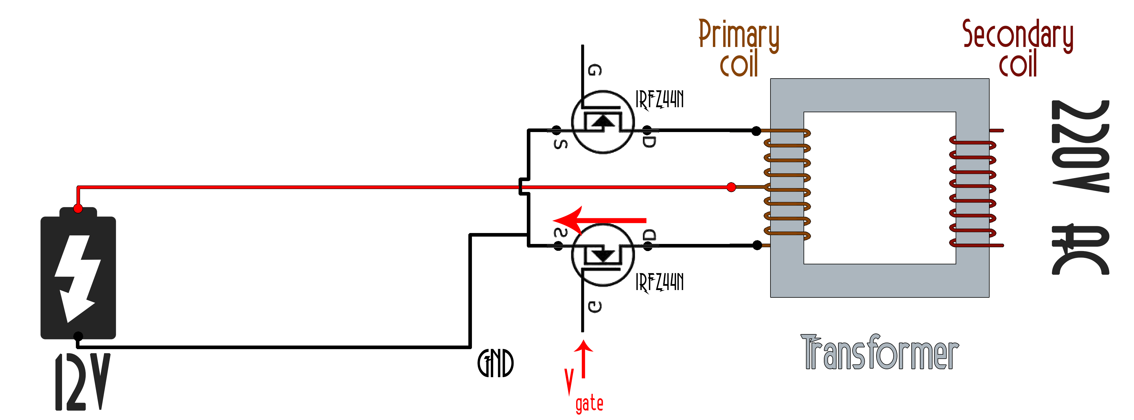
Diy Inverter Tutorial Arduino Or 555 Youtube The frequency is around 50 hz set by the 50 k preset at pin#7 of the ic 555. 6) ic 555 inverter with automatic arduino battery charger. in this 6th inverter design we use a 4017 decade counter and a ne555 timer ic are used to generate a sinewave pwm signal for the inverter and an arduino based automatic high low battery cut off with alarm. The 555 timer ic is used as the key component which is configured as an astable multivibrator to provide continuous switching pulses. the transformer has 230v 9v is used inverted to act as a step up transformer and is derived by the two transistors tip41a (npn) and tip42a (pnp). the input supply voltage is 5v to 15v dc and the output achieved. The major component in this simple inverter circuit using ic 555 is the timer ic555, which is set as an astable multivibrator to provide a continuous switching pulse. two switching transistors tip41a (npn) and tip42a (pnp) drive the transformer according to the pulse input at the base. t1 is a 230v primary to 9v secondary transformer that is. The project is made for arduino enthusiast; similar project can also be accomplished with transistors or ic 555 or ic 4047 etc. the advantage of using arduino is we can customize the output parameters, and mainly we can upgrade this square wave inverter to pure sine wave inverter by just writing a new code without any hardware changes (program only given for square wave).

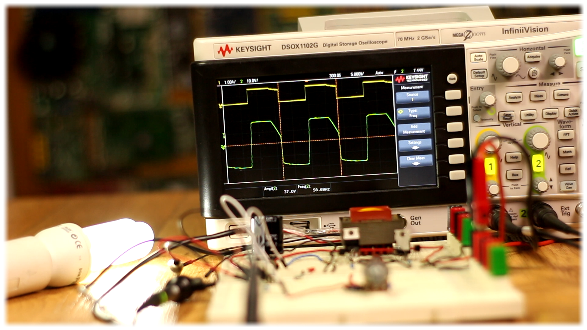
Homemade Inverter Diy Arduino 555 Timer Circuit The major component in this simple inverter circuit using ic 555 is the timer ic555, which is set as an astable multivibrator to provide a continuous switching pulse. two switching transistors tip41a (npn) and tip42a (pnp) drive the transformer according to the pulse input at the base. t1 is a 230v primary to 9v secondary transformer that is. The project is made for arduino enthusiast; similar project can also be accomplished with transistors or ic 555 or ic 4047 etc. the advantage of using arduino is we can customize the output parameters, and mainly we can upgrade this square wave inverter to pure sine wave inverter by just writing a new code without any hardware changes (program only given for square wave). The frequency of the ic 555 is determined by: f = 1.44 (r1 2 x r2) c. f = 1.44 (4700 2 x 120000) x 0.1 x 10^ 6. f = 58.84 hz. in real life we will get around 55 hz (depending on tolerance of components used) which is good enough for low power application like chargers, cfl lamps, table fans, tube lights, incandescent lamps etc. The above explained 1kva sinewave inverter circuit can be also driven through an arduino for achieving almost a prefect sinewave output. the complete arduino based circuit diagram can be seen below: program code is given below: connect pin 9 > 10k ohm (series with)100nf ceramic cap > gnd, tap the sinewave signal from the point at between.

Homemade Inverter Diy Arduino 555 Timer Circuit The frequency of the ic 555 is determined by: f = 1.44 (r1 2 x r2) c. f = 1.44 (4700 2 x 120000) x 0.1 x 10^ 6. f = 58.84 hz. in real life we will get around 55 hz (depending on tolerance of components used) which is good enough for low power application like chargers, cfl lamps, table fans, tube lights, incandescent lamps etc. The above explained 1kva sinewave inverter circuit can be also driven through an arduino for achieving almost a prefect sinewave output. the complete arduino based circuit diagram can be seen below: program code is given below: connect pin 9 > 10k ohm (series with)100nf ceramic cap > gnd, tap the sinewave signal from the point at between.

Comments are closed.