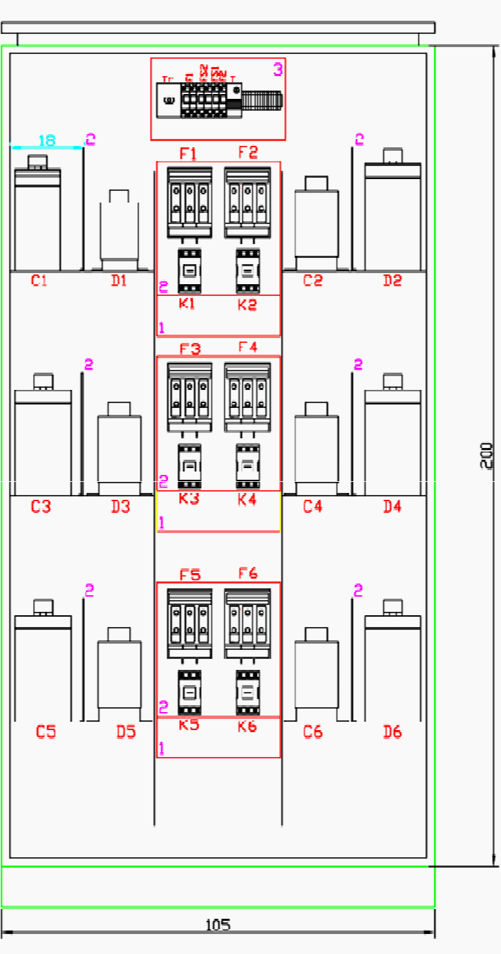
Diagram Wiring Diagram Panel Capacitor Bank Mydiagram Online

Diagram Wiring Diagram Panel Capacitor Bank Mydiagram Online A typical capacitor bank wiring diagram consists of two main components; the capacitor bank itself (also referred to as a ‘capacitor’ or ‘bank’) and the associated wiring. the capacitor bank provides the source of power for the rest of the diagram, typically having several capacitors connected in parallel with each other. A capacitor bank control wiring diagram is an electrical diagram that shows the physical wiring between components and devices—like circuit breakers, starters, transformers, and other electrical circuits. simply put, it's a map of how power flows through your home's electrical system. it is typically used to help troubleshoot problems.
Diagram Wiring Diagram Panel Capacitor Bank Mydiagram Online Excellent. the aim of project called „reactive power compensation panel” was to design capacitor bank with rated power of 200kvar and rated voltage of 400v adapted for operation with mains, where higher order harmonics are present. the capacitor bank was to be power capacitor based with automatic control by power factor regulator. Example of a 3 phase capacitor bank wiring diagram(this section would typically include an image of a wiring diagram for reference. however, as per the instructions, i cannot include images.) the diagram would typically show the three phase conductors connected to the capacitor bank, either in a delta or wye configuration. Schematic diagram of the capacitor bank pulsed power system scientific. amendments in technical specification no s 137 dd 177 july 2007 for 11kvautomatic switched capacitor bank at sub stations 33 1. basic circuit of a capacitor bank l c r and represent the wiring scientific diagram. step by tutorial for building capacitor bank and reactive. The main components of a power factor capacitor bank wiring diagram include the generator, breakers, capacitor, phase shift, latency covers, ground electrification controllers, conductors and terminals. additionally, the wiring diagram provides an indication of the size, voltage type and amperage requirements each component requires.
Diagram Wiring Diagram Panel Capacitor Bank Mydiagram Online Schematic diagram of the capacitor bank pulsed power system scientific. amendments in technical specification no s 137 dd 177 july 2007 for 11kvautomatic switched capacitor bank at sub stations 33 1. basic circuit of a capacitor bank l c r and represent the wiring scientific diagram. step by tutorial for building capacitor bank and reactive. The main components of a power factor capacitor bank wiring diagram include the generator, breakers, capacitor, phase shift, latency covers, ground electrification controllers, conductors and terminals. additionally, the wiring diagram provides an indication of the size, voltage type and amperage requirements each component requires. One of the essential things that must be taken into account after calculating the total and demand load of the project is to consider the power factor. inside the capacitor bank: power factor correction, circuits, calculation and schematics. but before indulging in the power factor correction, you should be aware of different types of loads. A capacitor bank has numerous advantages and applications. most of the time, these are used for reactive power compensation and power factor improvement. the arrangement of these can be done at substation or power plants. the unit for capacitance in farads. a capacitor bank of lower scale is frequently used in industrial buildings, college.

Diagram Wiring Diagram Panel Capacitor Bank Mydiagram Online One of the essential things that must be taken into account after calculating the total and demand load of the project is to consider the power factor. inside the capacitor bank: power factor correction, circuits, calculation and schematics. but before indulging in the power factor correction, you should be aware of different types of loads. A capacitor bank has numerous advantages and applications. most of the time, these are used for reactive power compensation and power factor improvement. the arrangement of these can be done at substation or power plants. the unit for capacitance in farads. a capacitor bank of lower scale is frequently used in industrial buildings, college.

Comments are closed.