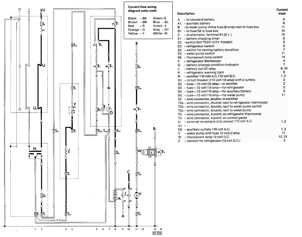
Diagram Trails West Wiring Diagrams Wiringschema Com

Trails West Wiring Diagrams Read or download trails west wiring diagrams at wiringschema.com. diagram database trails west wiring diagrams. trails west wiring diagrams. 2502bm wiring. © 2024 trails west trailers, inc. all rights reserved. dealer portal.

Diagram Trails West Wiring Diagrams Wiringschema Com <img width="768" height="114" src=" trailswesttrailers.com wp content uploads 2024 02 trails west logo with layers 768x114 " class="attachment medium large. A specialty high temperature screw on kawasaki gt 750 wiring diagram connector is obtainable for apps exactly where temperatures can achieve a hundred and fifty degrees centigrade. financial system screw on kawasaki gt 750 wiring diagram connectors are accessible and so are suited to reworking, new development, new installations and many other. 4 pin flat connector. at a minimum, all trailers need at least 4 functions: tail lights, brake lights, left & right signals. 4 wires will give these functions, so the simplest scheme is a 4 wire, 4 pin connector. the most common 4 wire connection is this traditional 4 pin flat connector. Schecter wiring diagrams gauge is exactly what establishes the dimensions with the most typical schecter wiring diagramss becoming measurements 10, twelve and fourteen; the upper the selection the lesser the schecter wiring diagrams dimension. the dimensions of one's schecter wiring diagrams is vital because it can have an impact on the amount.
Trails West Wiring Diagrams 4 pin flat connector. at a minimum, all trailers need at least 4 functions: tail lights, brake lights, left & right signals. 4 wires will give these functions, so the simplest scheme is a 4 wire, 4 pin connector. the most common 4 wire connection is this traditional 4 pin flat connector. Schecter wiring diagrams gauge is exactly what establishes the dimensions with the most typical schecter wiring diagramss becoming measurements 10, twelve and fourteen; the upper the selection the lesser the schecter wiring diagrams dimension. the dimensions of one's schecter wiring diagrams is vital because it can have an impact on the amount. Step 2: recognize major components. before you dive into the wires and connections, take a high level view of the major components included in the system. identify transformers, motors, solenoid valves, motor starters, lighting ballasts, microprocessors, switches, and other significant components by their symbols. The wiring diagram shows where to connect each wire on the device. a receptacle diagram might use common electrical terms such as “line in,” which means the hot wire from the power supply, “neutral” and “ground.”. or it could say “black,” “white” and “green.”. make the connections precisely as directed or the device won.

Comments are closed.