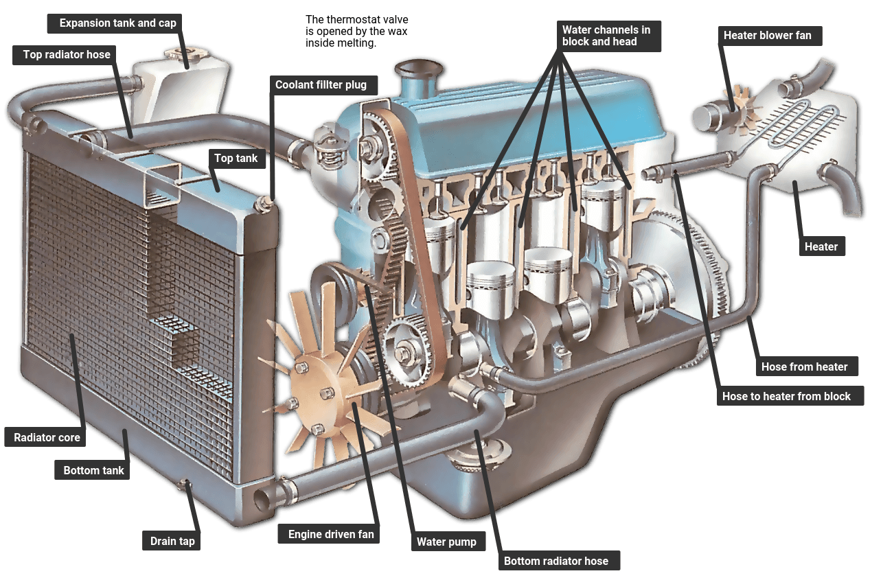
Cooling Water Circuit Diagram

Schematic Diagram Of The Cooling Water Circuit Download Scientific The local climate affects the temperature of the cooling water and air. in general, cooling systems are designed considering the cooling requirements under the least favorable climatic conditions that can occur locally, i.e. with design values of wet and dry bulb temperatures. these data should be stated in bedd. Chilled water schematic and condenser water schematic, how to read and understand the engineering drawings with real world examples, illustrations, animations and video tutorial. covering chillers, pump sets, ahus, risers, primary and secondary systems, cooling towers and bypass lines.

Cooling Water Circuit Diagram The chiller is responsible for cooling the water that circulates through the system. the chilled water leaves the chiller and enters a system of pipes that distribute it to various parts of the building or facility. a key element in the chilled water schematic diagram is the cooling coils, which are located in air handling units or fan coil units. Common cooling water issues cooling water has many enemies. sometimes they work alone. in other instances, they team up and compound the problem. for example, algae growth creates the perfect environment for corrosion to take hold. here’s a quick look at the major sources of cooling water fouling. scale and scalelike deposits include calcium. Introduction to cooling water system fundamentals. cooling of process fluids, reaction vessels, turbine exhaust steam, and other applications is a critical operation at thousands of industrial facilities around the globe, such as general manufacturing plants or mining and minerals plants. cooling systems require protection from corrosion. The closed recirculating cooling water system evolved from methods used for the cooling of early engine designs. in a closed water system, water circulates in a closed cycle and is subjected to alternate cooling and heating without air contact. heat, absorbed by the water in the closed system, is normally transferred by a water to water.

Cooling Water Circuit For The One Accelerating Structure And The Introduction to cooling water system fundamentals. cooling of process fluids, reaction vessels, turbine exhaust steam, and other applications is a critical operation at thousands of industrial facilities around the globe, such as general manufacturing plants or mining and minerals plants. cooling systems require protection from corrosion. The closed recirculating cooling water system evolved from methods used for the cooling of early engine designs. in a closed water system, water circulates in a closed cycle and is subjected to alternate cooling and heating without air contact. heat, absorbed by the water in the closed system, is normally transferred by a water to water. Once through cooling water system diagram . 1.2 open recirculating cooling water systems. open recirculating cooling water systems are open to the atmosphere and continuously recycle and reuse the cooling water. these systems are composed of an evaporator unit, a cooling tower, or an evaporative condenser. Sequence of operation. when the operating fan(s) are operating at 50 percent speed, an additional fan shall be enabled and controlled at the same speed as the operating fans until all active cooling tower cell fans are enabled. when operating fans are running at minimum speed and the tower supply water temperature is five (5) degrees below the.

Cooling Water Circuit Diagram Once through cooling water system diagram . 1.2 open recirculating cooling water systems. open recirculating cooling water systems are open to the atmosphere and continuously recycle and reuse the cooling water. these systems are composed of an evaporator unit, a cooling tower, or an evaporative condenser. Sequence of operation. when the operating fan(s) are operating at 50 percent speed, an additional fan shall be enabled and controlled at the same speed as the operating fans until all active cooling tower cell fans are enabled. when operating fans are running at minimum speed and the tower supply water temperature is five (5) degrees below the.

Comments are closed.