Cooling Tower Bypass Diagram

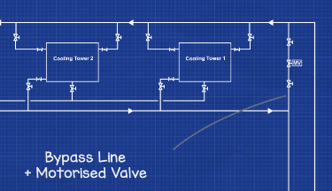
Cooling Tower Bypass Line The Engineering Mindset Cooling tower bypass pipework [3] a cooling tower bypass is used mainly in colder climates, where there is risk that the supply water temperature to the condenser side of the chillers is not at the required temperature set point, i.e its to cold system. When designing a cooling tower system for free cooling applications, several piping details should be considered to ensure proper winter operation of the unit. a cooling tower bypass needs to be incorporated into the system design to allow water to “bypass” the tower’s water distribution system as a means of capacity.

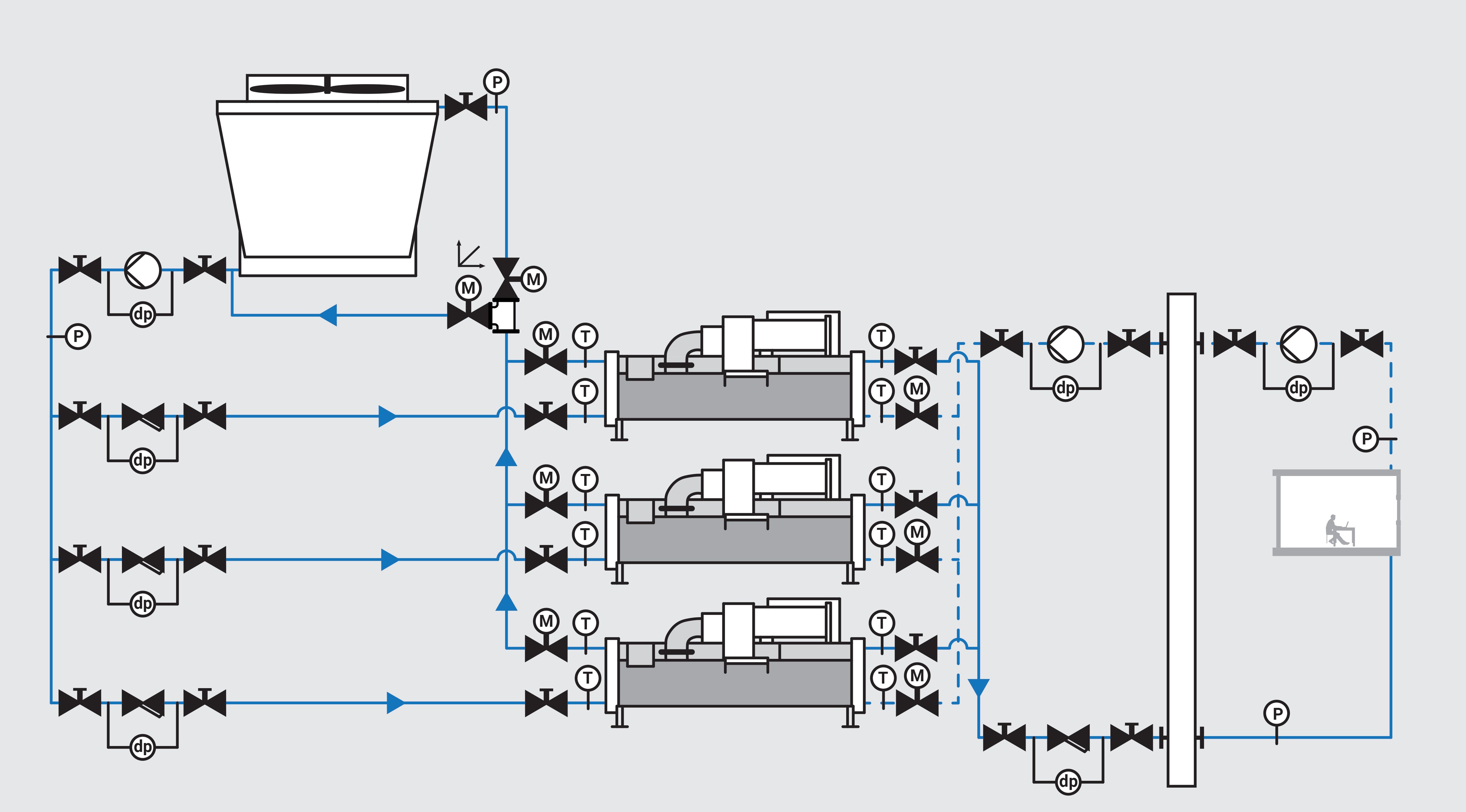
Isolation Of Chillers And Bypass In Closed Cooling Tower Troubles do occur occasionally, however, and these troubles can be classified as caused by: 1. incorrect pump head estimation. 2. pump cavitation and loss of pumping ability, as caused by inadequate pump suction pressure. 3. air in pump suction; as caused by tower pan vortex, pan drain down or faulty bypass. 4. Sequence of operation. when the operating fan(s) are operating at 50 percent speed, an additional fan shall be enabled and controlled at the same speed as the operating fans until all active cooling tower cell fans are enabled. when operating fans are running at minimum speed and the tower supply water temperature is five (5) degrees below the. Understanding the basics of piping and controls is step number one in the cooling tower industry. but how effectively a cooling tower piping system is designed and installed can have a critical impact on system efficiency, functionality and even safety. properly engineered condenser, chiller and cooling tower piping and controls will improve heat transfer and avoid problems such as air. Depending on cooling requirements, one, two, or three chillers are in operation. manual open close butterfly valves isolate the pumps, chillers, cooling towers, and strainers during commissioning or maintenance. the 3 way control butterfly valve (diverting valve) performs temperature control on the cooling tower so that the downstream entry.

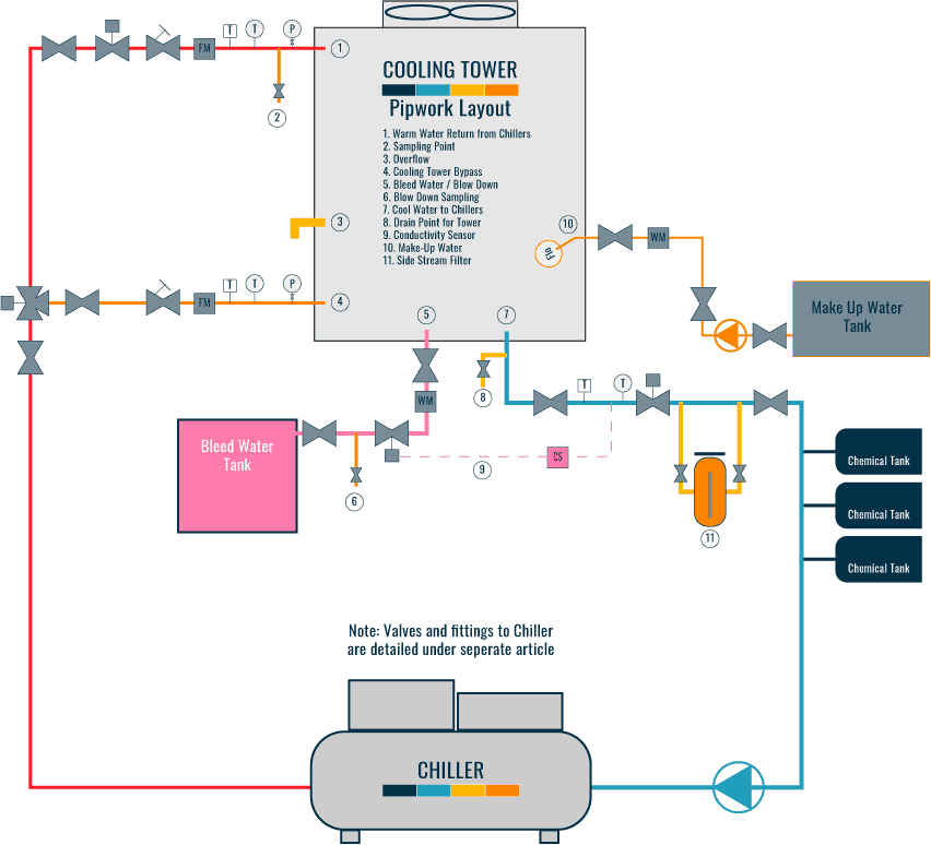
Cooling Tower Piping Layout And Diagrams Constructandcommission Understanding the basics of piping and controls is step number one in the cooling tower industry. but how effectively a cooling tower piping system is designed and installed can have a critical impact on system efficiency, functionality and even safety. properly engineered condenser, chiller and cooling tower piping and controls will improve heat transfer and avoid problems such as air. Depending on cooling requirements, one, two, or three chillers are in operation. manual open close butterfly valves isolate the pumps, chillers, cooling towers, and strainers during commissioning or maintenance. the 3 way control butterfly valve (diverting valve) performs temperature control on the cooling tower so that the downstream entry. Counterflow cooling tower diagram difference between crossflow and counterflow cooling towers: in counterflow cooling tower system processes, the air vertically flows upwards, counter to the water flow in the fill media. due to the air flowing vertically, it's not possible to use the basin's gravity flow like in crossflow towers. 5 at uat 1,2 m wide units. 6 at uat 2,4 and 2,6 m wide cells. download this manual. operation and maintenance instructions. for evapco induced draft and forced draft cooling towers. at. evapco, inc. (world headquarters) p.o. box 1300, westminster, maryland 21158 usa. evapco europe. bvba.

Comments are closed.