Cooling Fan Circuit Diagram 05 Quest

Cooling Fan Circuit Diagram 05 Quest Cooling fan relay 2: h: 40: cooling fan relay 1, cooling fan relay 3: i: 40: circuit breaker 1 (slide door auto closure system, power seat) j: 50: body control module (bcm) k: 40: ignition switch: l: 40: abs: m: 40: circuit breaker 2 (adjustable pedal system, automatic drive positioner, slide door auto closure system, power seat) relays: r1. On the fuse diagram, find the number of the fuse you want to check. the diagram tells you where to locate the fuse on the panel. pinch the fuse perpendicularly with the fuse puller and pull it out. to check a fuse, look at the silver colored band inside the fuse. if the band is broken or melted, replace the fuse with a new one.

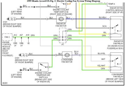
Cooling Fan Circuit Diagram 05 Quest The fsm also describes testing the various harnesses and connections between the relays, fan motors, and the cpu. the cpu is supplying the 12v to the motor windings and the relay operation supplies the ground. the relays supply ground to various windings of the motors for the different speeds. the fsm also cautions not to overheat the engine. Using the dodge radiator fan wiring diagram above, you’ll see that the relay ground is at g102 and the control coil receives power from the pcm. the pcm won’t provide power until the engine coolant temperature sensor reading reaches the set amount. 2008 nissan quest wiring diagrams free download as pdf file (.pdf), text file (.txt) or read online for free. 2008 nissan quest wiring diagrams. Step 4: relay test. if your fan wiring includes a relay, it is important to test it as well. check for continuity across the relay terminals when the fan is supposed to be on. if there is no continuity, there may be a problem with the relay and it may need to be replaced.

Cooling Fan Circuit Diagram 05 Quest 2008 nissan quest wiring diagrams free download as pdf file (.pdf), text file (.txt) or read online for free. 2008 nissan quest wiring diagrams. Step 4: relay test. if your fan wiring includes a relay, it is important to test it as well. check for continuity across the relay terminals when the fan is supposed to be on. if there is no continuity, there may be a problem with the relay and it may need to be replaced. Start with taking both of the positive wires from the fans and connect them to the yellow wires on each relay. you will then need to run switched power (usually from your ignition switch, but modern replacement wiring harnesses usually have a fused fan relay trigger wire) to the blue wires on the relays. next, both of the black wires from the. It is used to indicate the presence of a fan in a circuit and its basic function. the fan schematic symbol consists of several components that represent different aspects of the fan. 1. motor: the motor component is usually represented by a circle with an “m” inside.

Comments are closed.